Eureka AIR delivers breakthrough ideas for toughest innovation challenges, trusted by R&D personnel around the world.

Shoes employing monitoring devices, and associated methods

a technology of monitoring device and shoe, applied in the field of sensing system monitoring application, can solve the problems of not being able to predict the movement detail, minute to minute, second to second, and still not generally determinable in the prior, and not providing for the knowledge of movemen

Inactive Publication Date: 2006-06-29
APPLE INC
View PDF9 Cites 377 Cited by
  • Summary
  • Abstract
  • Description
  • Claims
  • Application Information

AI Technical Summary

Benefits of technology

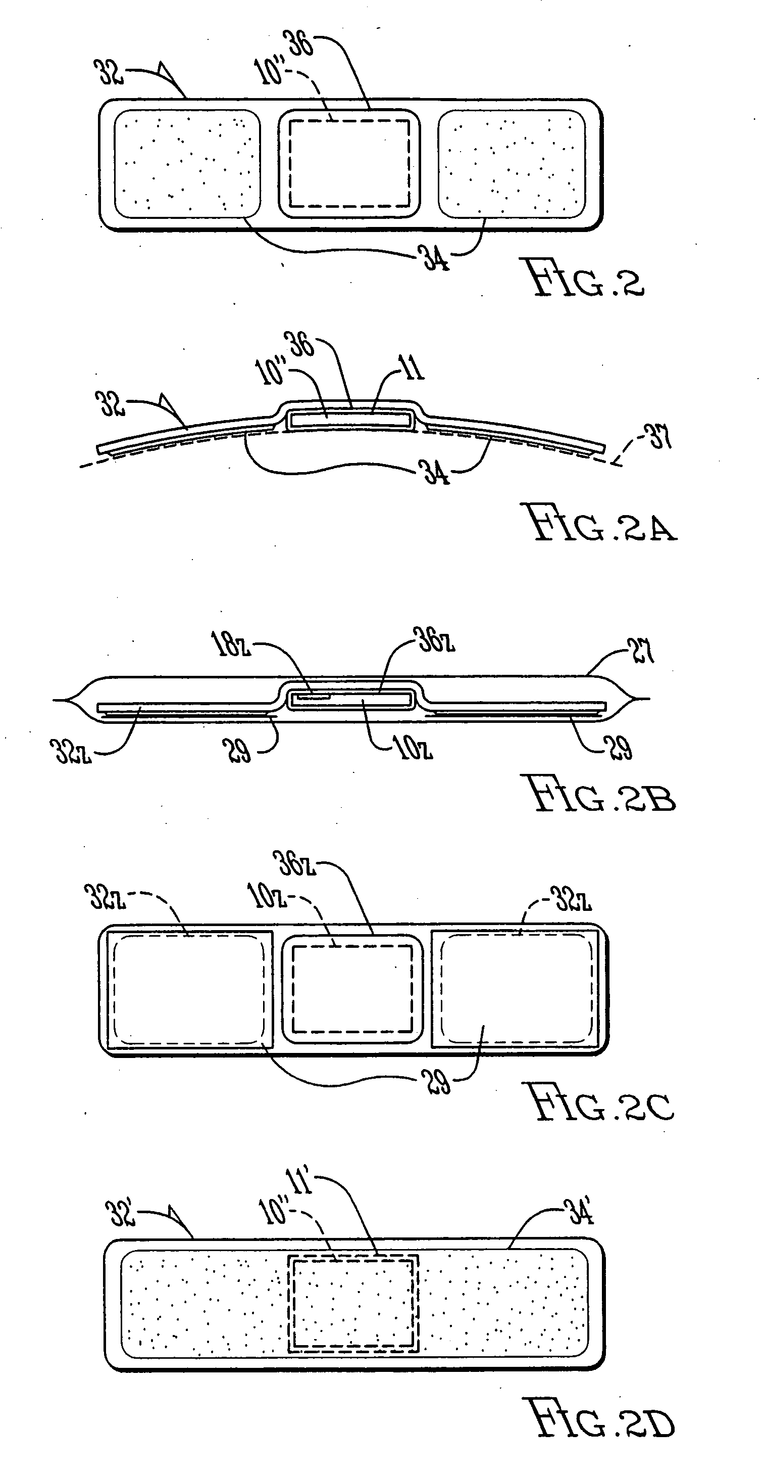
[0008] In yet another aspect, the MMD with adhesive strip collectively take a form similar to an adhesive bandage. More particularly, the adhesive strip of the invention is preferably like or similar to the adhesive of the adhesive bandage; and the processor (or protective wrapper) is embedded with the strip much the way the cotton is with the adhesive bandage. Preferably, a soft material (e.g., cotton or cloth) is included to surround the processor so as to (a) soften contact of rigid MMD components with a person and / or (b) protect the processor (and / or other components of the MMD). In still another aspect, the battery is also coupled with the soft material. In still another aspect, the processor and other elements of the MMD are combined into a single system-on-chip integrated circuit. A protective cover may surround the chip to protect the MMD from breakage.
[0076] In one aspect, the EMD continuously relays an environmental metric (e.g., temperature, humidity, or chemical content) by continuous transmission of data from the detector to a RR. In this way, a EMD attached to a person or object may beneficially track conditions, in real time, of that person or object by recombination of the environmental metrics at a remote computer. In one aspect, multiple EMDs attached to a person or object quantify data for a plurality of locations, for example to monitor sub-parts of an object or person.

Problems solved by technology

However, the detail of movement, minute to minute, second to second, is still not generally determinable in the prior art.
Body movement involved in transportation is subjected to many forces, some of which are dangerous.
But the prior art does not provide for this knowledge; there is no effective way, currently, to efficiently quantify human movement.

Method used


Image

  • Shoes employing monitoring devices, and associated methods
  • Shoes employing monitoring devices, and associated methods
  • Shoes employing monitoring devices, and associated methods

Examples


Embodiment Construction

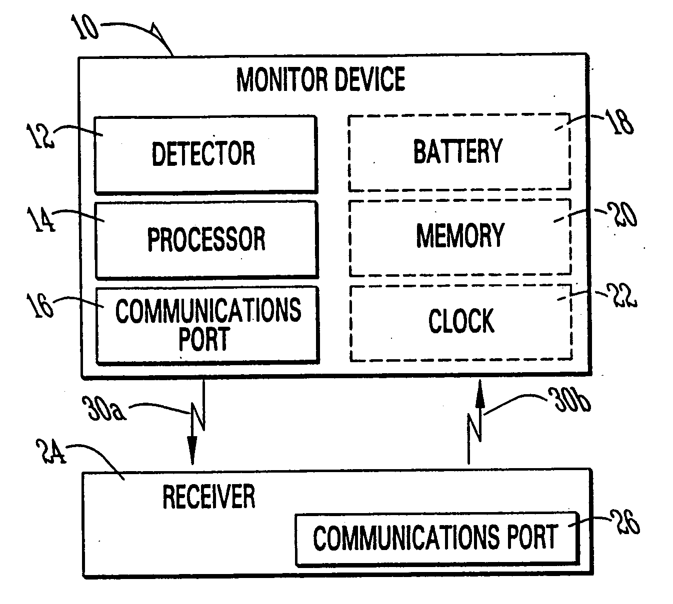
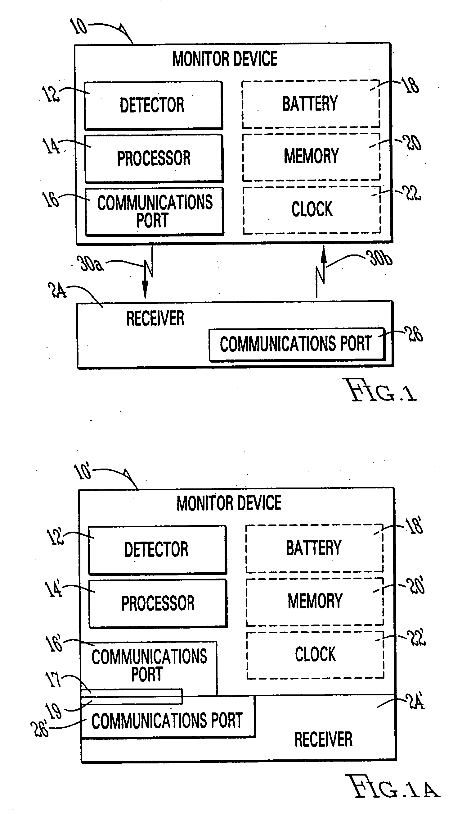
[0191]FIG. 1 shows a monitor device 10 constructed according to the invention. Device 10 can for example operate as a MMD or EMD described above. Device 10 includes a detector 12, processor 14, communications port 16, and battery 18. Preferably, device 10 also includes solid-state memory 20. Memory 20 can be integral with processor 14 (or other element of device 10, including port 16), or a stand-alone element within device 10. As a MMD, for example, detector 12 senses movement experienced by device 10 and generates signals indicative of that movement. Processor 12 then processes the signals to extract desired movement metrics, as described herein. Typically, when the movement metrics exceed a predetermined threshold, processor 12 stores data as an “event” within memory 20. Events are also preferably tagged with time information, typically date and time, as provided by clock 22.

[0192] As an EMD, for example, detector 12 senses temperature experienced by device 10 and generates sign...


PUM


Abstract

Methods are disclosed for determining speed or distance traveled of moving persons by utilizing sensors in shoes. Methods and systems are disclosed to determine and report weight of a person wearing a shoe via a sensor with the shoe. Shoe based systems employing sensors (e.g., accelerometers) are disclosed to determine and report (e.g., via a watch) speed and / or distance traveled.

Description

[0001] This application is a continuation of application Ser. No. 10 / 601,208 filed Jun. 20, 2003 and a continuation of application Ser. No. 10 / 297,270 filed Dec. 4, 2002, which claims priority to PCT Application No. PCT / US01 / 51620, filed Dec. 17, 2001 and to the following six U.S. provisional applications: U.S. Provisional Application No. 60 / 256,069, filed Dec. 15, 2000; U.S. Provisional Application No. 60 / 257,386, filed Dec. 22, 2000; U.S. Provisional Application No. 60 / 259,271, filed Dec. 29, 2000; U.S. Provisional Application No. 60 / 261,359, filed Jan. 13, 2001; U.S. Provisional Application No. 60 / 285,032, filed Apr. 19, 2001; and U.S. Application No. 60 / 323,601, filed Sep. 20, 2001. The foregoing applications are expressly incorporated herein by reference.FIELD OF THE INVENTION [0002] The invention relates to sensing systems monitoring applications in sports, shipping, training, medicine, fitness, wellness and industrial production. The invention specifically relates to sensing ...

Claims


Application Information

Patent Timeline
IPC IPC(8): H04N7/16G16Z99/00
CPCA43B3/00A43B3/0005A43B5/06A61B5/0002A61B5/1112A61B5/1117A61B5/1126A61B5/113A61B5/6807A61B5/6833A61B2503/10A61B2562/0219A61B2562/08A61B2562/242A63B24/0062A63B69/00A63B69/0028A63B71/0605A63B2208/12A63B2220/20A63B2220/30A63B2225/50A63B2230/01A63B2244/10G01C22/006G01G19/44G01G23/00G01G23/3728G01P1/127G01P15/0891G06Q10/08G06Q10/083G06Q10/0833A61B2560/0412G01B7/004G01P3/00G01B21/00G06F19/00G16Z99/00A43B3/34G01P15/02
Inventor VOCK, CURTIS A.AMSBURY, BURL W.EDSTROM, ERIC R.HOLME, ROBERT MUIRJONJAK, PAULLARKIN, ADRIAN F.YOUNGS, PERRY
Owner APPLE INC
Why Eureka
Eureka Blog
Learn More