
Optical recording material and optical recording medium

Inactive Publication Date: 2006-06-29
TDK CORPARATION
View PDF2 Cites 3 Cited by
  • Summary
  • Abstract
  • Description
  • Claims
  • Application Information

AI Technical Summary

Benefits of technology

[0012] In recent years there has been a need for higher bit densities in recording layers to allow recording of greater volumes of data on optical recording media, as well as a demand for higher speeds in linear recording (recording speeds) of information in order to shorten recording times.
[0023] However, the present inventors believe that when high energy laser light is irradiated in sections with recording patterns wherein the distances between recording pits are short, the laser-generated heat is readily transferred to adjacent pits with increasing recording speed, tending to produce frequent heat interference between the pits. With high-speed recording of information at 4× speed or higher, i.e. a linear speed of 14 m / sec or greater, the heat interference between pits presumably results in increased jitter and a higher error rate.
[0026] The azo compound of the optical recording material of the invention preferably includes an azo compound represented by the following general formula (1) for further enhanced recording characteristics and light stability.

Problems solved by technology

However, based on detailed research by the present inventors with regard to conventional optical recording media including those described in the aforementioned patent documents, it was found that it is difficult to ensure sufficient recording characteristics during high-speed recording even when such dye components satisfying the conventional evaluation criteria are used in optical recording media.
That is, it was found that when dye components satisfying the evaluation criteria described in the aforementioned patent documents are used as constituent materials of recording layers in order to achieve higher recording speeds, it becomes difficult to obtain the desired pit lengths, resulting in a tendency toward increased jitter and a higher error rate.

Method used


Image

  • Optical recording material and optical recording medium
  • Optical recording material and optical recording medium
  • Optical recording material and optical recording medium

Examples


example 1

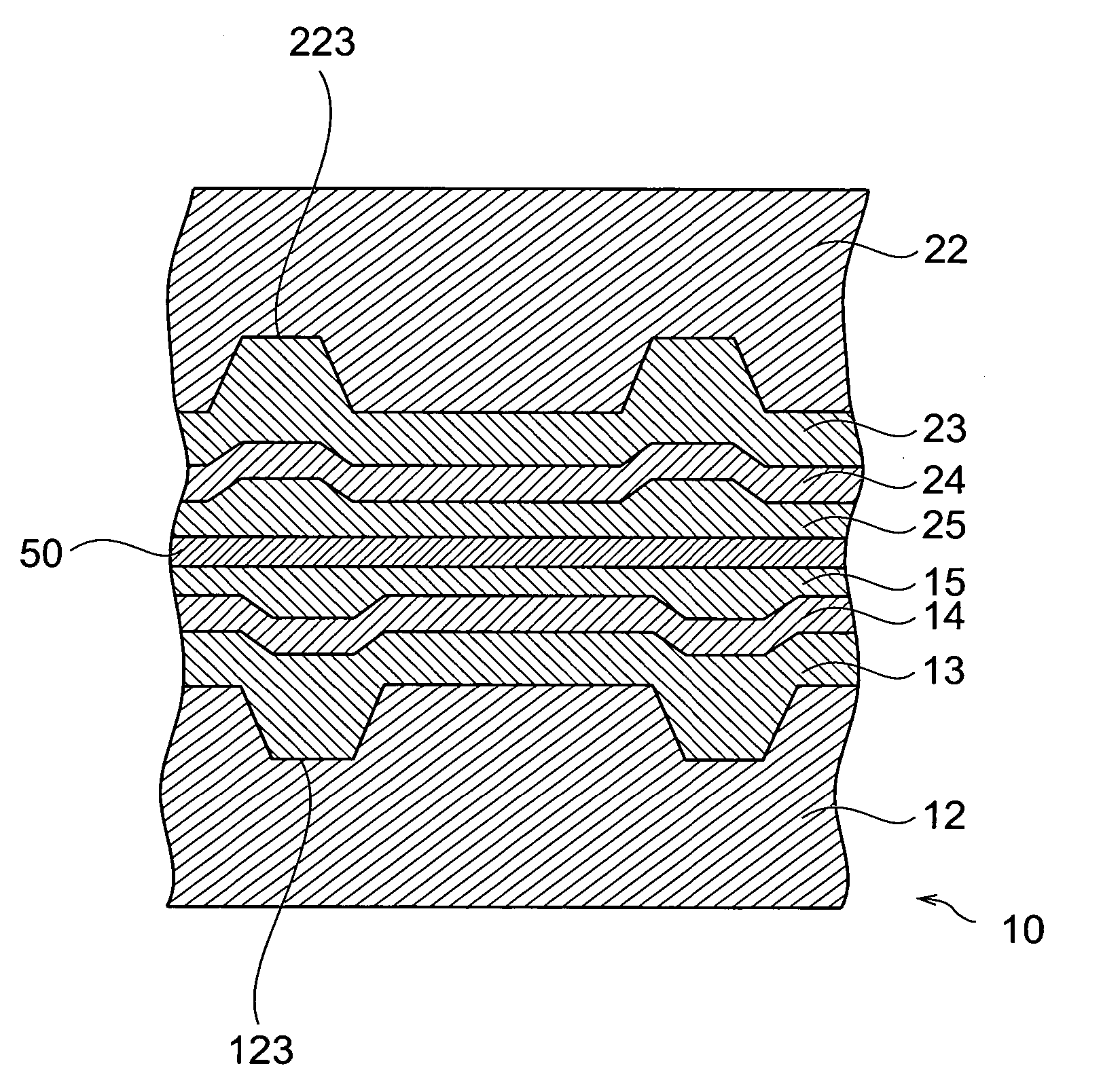
[0100] First, a polycarbonate resin base with a 120 mm diameter and a 0.6 mm thickness was prepared, having a pre-groove (0.12 μm depth, 0.30 μm width, 0.74 μm groove pitch) formed on one side. Separately, a dye component composed of the same material as sample No. 1 was added to 2,2,3,3-tetrafluoropropanol to a content of 1.0 wt % to prepare a recording layer coating solution. The obtained coating solution was applied onto the side of the aforementioned polycarbonate resin base on which the pre-groove had been formed, and dried at 80° C. for 1 hour to form a recording layer (150 nm thickness). Next, an Ag reflective film (100 nm thickness) was formed on the recording layer by sputtering, and an ultraviolet curing resin SD-1700 (trade name of Dainippon Ink & Chemical Industries Co., Ltd.) was coated onto the Ag reflective layer by spin coating and then subjected to ultraviolet irradiation to form a transparent protective layer (8 μm thickness) composed of an acryl resin. Also, an ul...


PUM

PropertyMeasurementUnit
Temperatureaaaaaaaaaa
Speedaaaaaaaaaa
Poweraaaaaaaaaa

Abstract

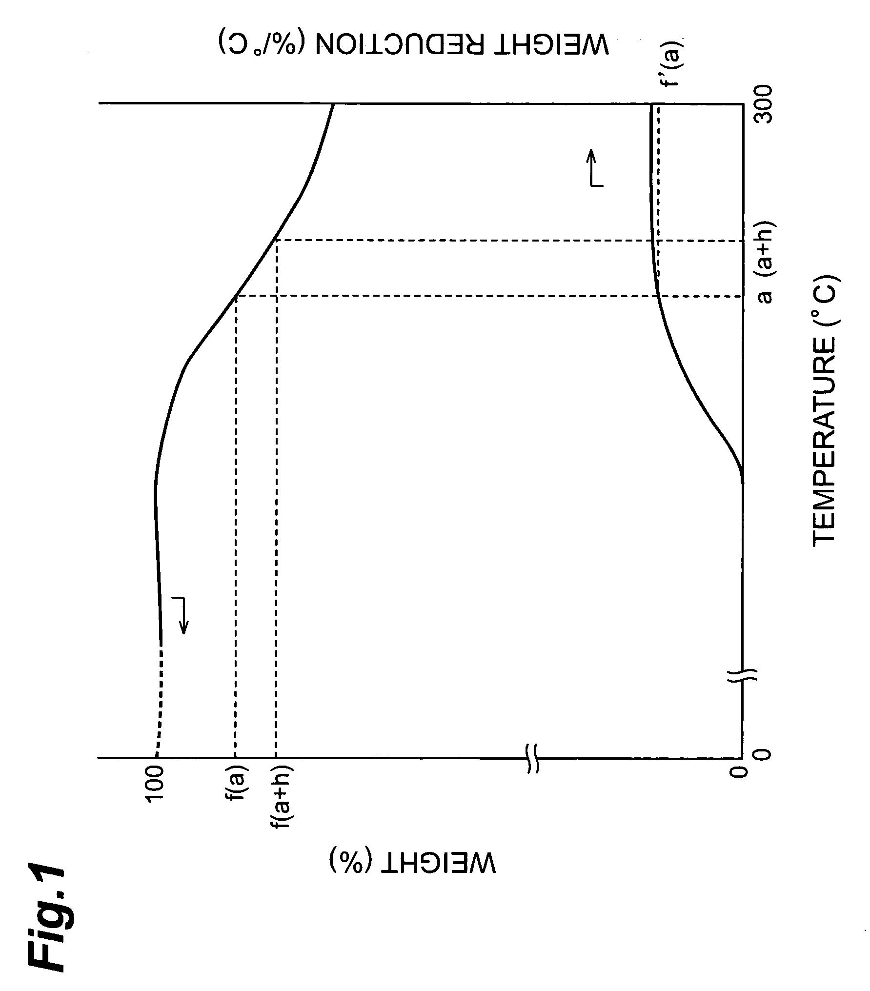
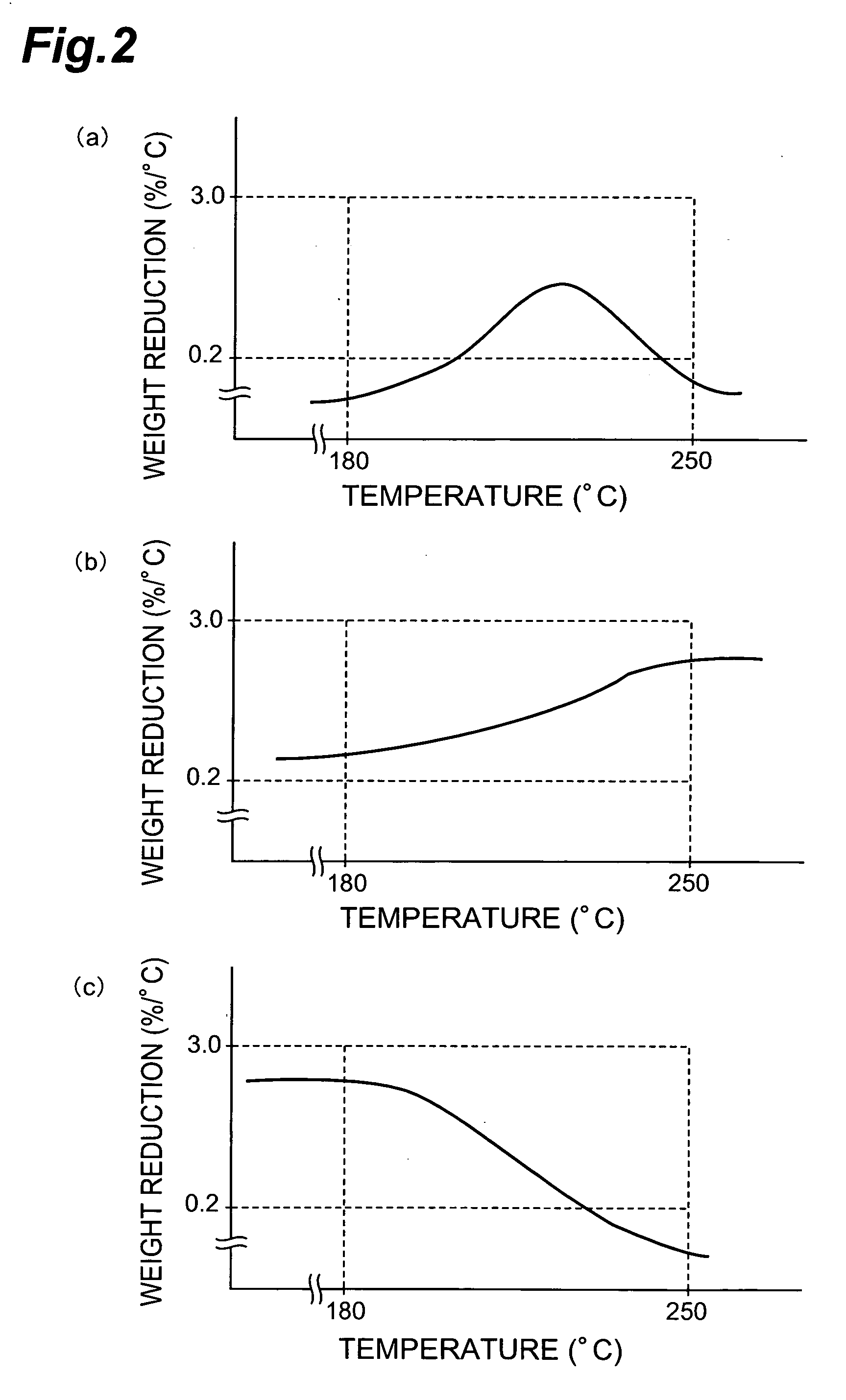
The optical recording material of the invention is an optical recording material used for an optical recording medium capable of recording information by irradiation of light, the optical recording medium being an optical recording medium which records information at a linear speed of at least 14 m / sec, wherein the dye component in the optical recording material comprises at least one type of chelate compound of an azo compound and a metal, and when the dye component is used as a sample for thermogravimetry in an inert gas atmosphere, the dye component sample exhibits a maximum weight reduction of 0.2-3.0% / ° C. at 180-250° C.

Description

BACKGROUND OF THE INVENTION [0001] 1. Field of the Invention [0002] The present invention relates to an optical recording medium for recording of information by irradiation of light, and to an optical recording material used in the medium. [0003] 2. Related Background of the Invention [0004] Conventional optical recording media record information by irradiation of light such as laser light on a recording layer to produce deformational changes, magnetic changes or phase changes in the recording layer. Such optical recording media include, for example, write-once optical recording media comprising recording layers which contain organic dyes such as azo compounds, and are widely used as CD-R (CD-Recordable) and DVD±R (DVD Recordable) media. [0005] Of the write-once optical recording media mentioned above, CD-R media are usually formed by laminating a recording layer containing a dye as the major constituent component, a reflective layer composed mainly of metal and a protective layer c...

Claims


Application Information

Patent Timeline
IPC IPC(8): B32B3/02B41M5/26G11B7/244G11B7/246G11B7/247G11B7/249
CPCG11B7/246G11B7/2463G11B7/2467G11B7/2472G11B7/2475G11B7/2478G11B7/249G11B7/2492G11B7/2498G11B7/2533G11B7/2534G11B7/2536G11B7/259G11B2007/24612C09B23/06C09B29/0003C09B29/0014C09B29/0048C09B29/0085C09B29/0811C09B45/22
Inventor MONDEN, ATSUSHISHINKAI, MASAHIROTANABE, JUNJI
Owner TDK CORPARATION
Learn More