
Element attachable by riveting to a sheet metal part and also a component assembly and a method for the production of the component assembly

Active Publication Date: 2006-06-29
HVB BANQUE LUXEMBOURG
View PDF1 Cites 35 Cited by
  • Summary
  • Abstract
  • Description
  • Claims
  • Application Information

AI Technical Summary

Benefits of technology

[0011] The object of the present invention is to provide an element of the initially named kind which can have a purely centering function as well as a centering and attachment function, with forces being required for the attachment to the sheet metal part which remain within acceptable limits even with shaft diameters of 12 mm and larger, with undesired deformation of the sheet metal part not having to be feared and with it being possible to use only one element with sheet metal parts of various thicknesses with an excellent resistance to rotation being achieved.
[0013] Through the provision of features providing security against rotation in the form of a local recess or of a plurality of uniformly distributed recesses in the conical wall of the ring recess and / or in a tubular base surface of the ring recess a situation is prevented, in particular with thicker metal sheets, that the features providing security against rotation represent a resistance during the attachment of the element to the sheet metal part which has first to be overcome for the shaping of the sheet metal part or for the reshaping of the rivet section. Furthermore, such recesses providing security against rotation lead to a situation in which no undesired deformation of the sheet metal part arises which is of particular significance for a centering element. Moreover, such recesses providing security against rotation ensure an adequate rotational security and do not prevent the rivet bead being formed such that it can be fully received within a ring recess present at the lower side of the sheet metal part, i.e. at the side of the sheet metal part remote from the head part of the element, so that a flat attachment surface is present at the lower side of the sheet metal part. This in turn gives the guarantee that the guide section of the element which brings about the centering can also be provided directly at the underside of the sheet metal part, i.e. at the free end face of the rivet bead which is present at the shaft part of the element so that an ideal centering or positioning of a component is ensured which is disposed over the guide section of the element.
[0015] The element in accordance with the invention also has the advantage that it is possible to carry out the so-called clamping hole riveting process in accordance with the European patent 0 539 793 B1 and to hereby achieve the desired stranglehold between the sheet metal part and the element. In other words the (partial) pressing flat of the conical raised portion can be exploited in order to reduce size of the central opening of a sheet metal part during the carrying out of the riveting process, so that the rim region of the opening enters into contact with the sheet metal of the element in the region above the rivet section or in the region of the rivet section while the latter is turned over radially outwardly through the riveting process and optionally radially expanded by the riveting process.
[0017] Even when the fastener element has a pure centering function it is favorable to provide the features providing security against rotation into the form of the local recess or recesses, since one can in this way provide a simple possibility of ensuring that the method for the attachment of the element to a sheet metal part takes place with the required process reliability. One can namely, after attachment of the element of the sheet metal part and with appropriate support of the sheet metal part apply torques to the element in an attempt to twist the element out of the sheet metal part or to loosen it in the sheet metal part. The level of the torque which arises is a measure as to how firmly the element is attached to the sheet metal part and can be used to ensure quality or to check quality.
[0023] In this embodiment the ring-like raised portion of the die button is formed at its free end at least substantially with a ring edge which merges into a rounded shaping surface disposed radially outside of the ring edge, whereby the rivet section is re-shaped into a rivet bead. In this connection the ring edge has a diameter which is smaller than that of the tubular rivet section in the region of the ring apex of the free end of the rivet section, so that the ring edge can deflect the rivet bead radially outwardly during the riveting process.

Problems solved by technology

Moreover, such recesses providing security against rotation ensure an adequate rotational security and do not prevent the rivet bead being formed such that it can be fully received within a ring recess present at the lower side of the sheet metal part, i.e. at the side of the sheet metal part remote from the head part of the element, so that a flat attachment surface is present at the lower side of the sheet metal part.
For example only two different elements are required to cover a range of sheet metal thicknesses from for example 0.6 to beyond 3.5 mm without the rivet bead which is positioned in the ring recess at the lower side of the sheet metal part projecting beyond the lower side of the sheet metal part and causing in difficulties during the attachment of the further component.

Method used


Image

  • Element attachable by riveting to a sheet metal part and also a component assembly and a method for the production of the component assembly
  • Element attachable by riveting to a sheet metal part and also a component assembly and a method for the production of the component assembly
  • Element attachable by riveting to a sheet metal part and also a component assembly and a method for the production of the component assembly

Examples


Embodiment Construction

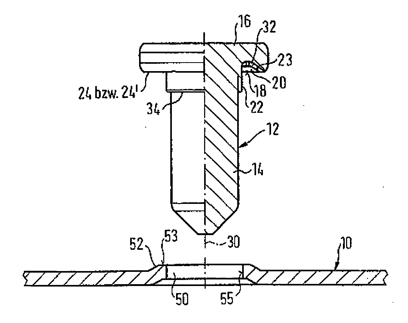
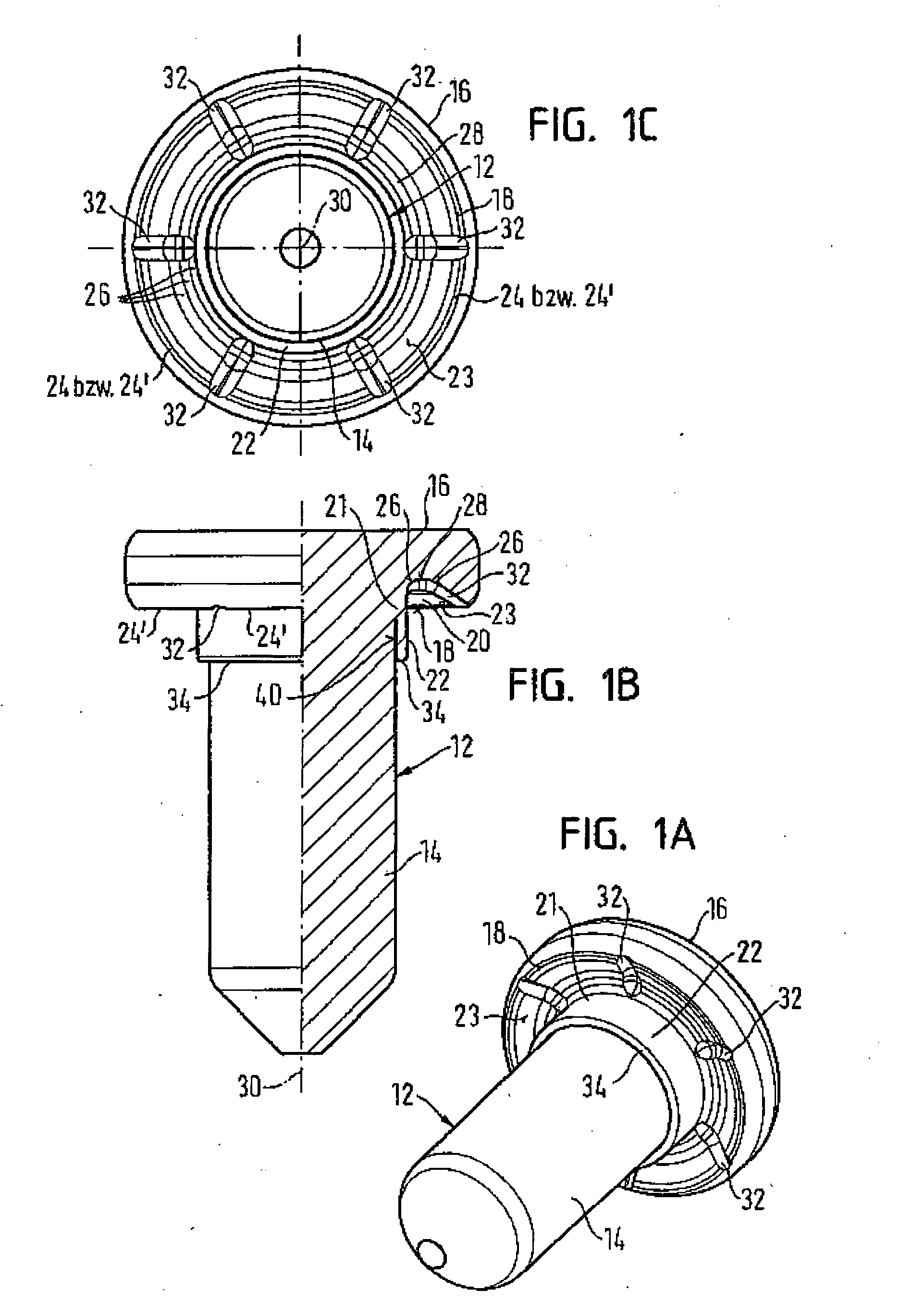
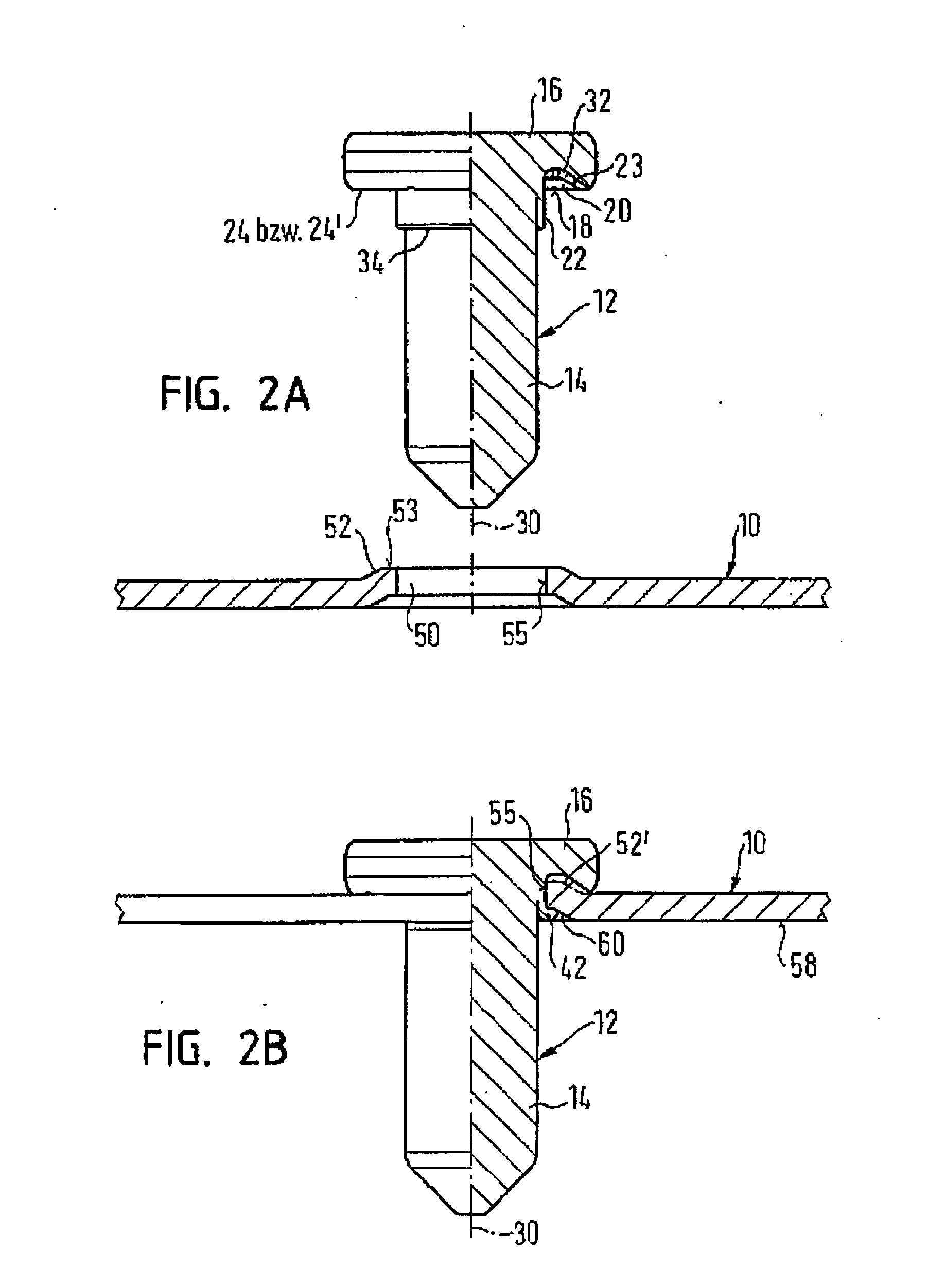
[0030] Referring to FIGS. 1A to 1C and FIGS. 2A to 2B an element 12 is shown which is attached to a sheet metal part 10 by riveting. The element 12 has the form of a centering element having a shaft part 14 and a head part 16, with the head part having an at least approximately ring-like recess 20 at its side 18 remote from the sheet metal part 10 with the ring recess merging at the radially inner side into a cylindrical section 21 of the head part 16 which in turn merges into the shaft part 14 and a tubular rivet section 22 which surrounds the shaft part 14 in the region of the head part 16, i.e. directly beneath the head part 16. The ring recess 20 is arranged within a ring-like contact surface 24 disposed radially outside of the ring recess, or radially outside of a contact surface consisting of circular ring segments 24′, and merges at the radially outer side via an at least approximately conical wall 23 into the contact surface 24 or 24′. The conical wall 23 can advantageously ...


PUM

PropertyMeasurementUnit
Diameteraaaaaaaaaa
Sizeaaaaaaaaaa
Shapeaaaaaaaaaa

Abstract

An element attachable to a sheet metal part by riveting, in particular an element in the form of a centering bolt, having a shaft part and a head part, wherein the head part has at its side confronting the sheet metal part an at least approximately ring-like ring recess which merges at the radially inner side into a cylinder section of the head part which in turn merges into the shaft part and into a tubular rivet section which surrounds the shaft part in the region of the head part, is disposed within a ring-like contact surface arranged radially outside of the ring recess and merges at the radially outer side via an at least approximately conical wall into the ring-like contact surface, is characterized in that at least one local recess and preferably a plurality of in particular uniformly distributed local recesses is or are provided in the conical wall of the ring recess and / or in an optionally present ring-like base surface of the ring recess. A component assembly comprising the element and a sheet metal part and also a method for the manufacture of such a component assembly are also described.

Description

FIELD OF THE INVENTION [0001] The present invention relates to an element attachable to a sheet metal part by riveting, in particular an element in the form of a centering bolt, having a shaft part and a head part, wherein the head part has at its side confronting the sheet metal part an at least approximately ring-like ring recess, which merges at the radially inner side into a cylinder section of the head part which in turn merges into the shaft part and into a tubular rivet section which surrounds the shaft part in the region of the head part, is disposed within a ring-like contact surface arranged radially outside of the ring recess and merges at the radially outer side via an at least approximately conical wall into the ring-like contact surface. Furthermore, the invention relates to a component assembly comprising a sheet metal part to which the element is attached and also a method for the attachment of the element to a sheet metal part. [0002] An element, a component assembl...

Claims


Application Information

Patent Timeline
IPC IPC(8): B21D39/00F16B37/06
CPCB23P19/062F16B37/065Y10T29/49938Y10T29/49936Y10T29/49915Y10T29/49925Y10T29/49956
Inventor BABEJ, JIRIHUMPERT, RICHARDVIETH, MICHAEL
Owner HVB BANQUE LUXEMBOURG
Learn More