
Magneto-resistive sensor with stopper layer and fabrication process

a technology of resistive sensor and stopper layer, which is applied in the field of magnetoresistive sensor, can solve the problems of difficult and achieve the effects of reducing the height of the resist mask, eliminating the fence, and reducing the difficulty of lifting off using cmp

Inactive Publication Date: 2006-06-22
WESTERN DIGITAL TECH INC
View PDF4 Cites 25 Cited by
  • Summary
  • Abstract
  • Description
  • Claims
  • Application Information

AI Technical Summary

Benefits of technology

[0013] It is a feature of the present invention to provide a method for fabricating a magneto-resistive sensor which solves the aforementioned problems of the prior art and in which the height of the resist mask is sufficiently secured and lift-off can be easily carried out by using CMP.
[0015] The RIE process can be omitted by substituting the first stopper layer composed of DLC with a metallic material. That is, by removing the unnecessary part of the first stopper layer simultaneously with the magnetoresistive film by IBE using Ar ions, a decrease in the height of the resist mask can be suppressed to the minimum and lift-off using CMP becomes easier. Especially, in the case when a resist pattern with a small track width or sensor height is used, lift-off and elimination of the fence become possible.
[0016] According to a method for fabricating a magneto-resistive sensor of the present invention, elimination of the fence and lift-off becomes possible even if a resist pattern with a small track width or sensor height is used because lift-off using CMP can be carried out more easily. Therefore, a magneto-resistive sensor can be provided in which the track width and the sensor height are small, and contact failure does not arise between the upper shield layer and the magnetoresistive film. Moreover, by mounting a magneto-resistive sensor fabricated by a fabricating method of the present invention in a magnetic storage, a magnetic storage having a high recording density can be achieved.

Problems solved by technology

As mentioned above, the problem of a lift-off technology by a conventional CMP using a stopper layer composed of DLC is in the point that the height of the resist mask becomes smaller when a narrower track width and a smaller sensor height have to be made according to a higher recording density, resulting in lift-off using CMP becoming difficult.
Herein, the former process is an unnecessary process in the typical process in which a lift-off technique using CMP is not used.

Method used


Image

  • Magneto-resistive sensor with stopper layer and fabrication process
  • Magneto-resistive sensor with stopper layer and fabrication process
  • Magneto-resistive sensor with stopper layer and fabrication process

Examples


embodiment 1

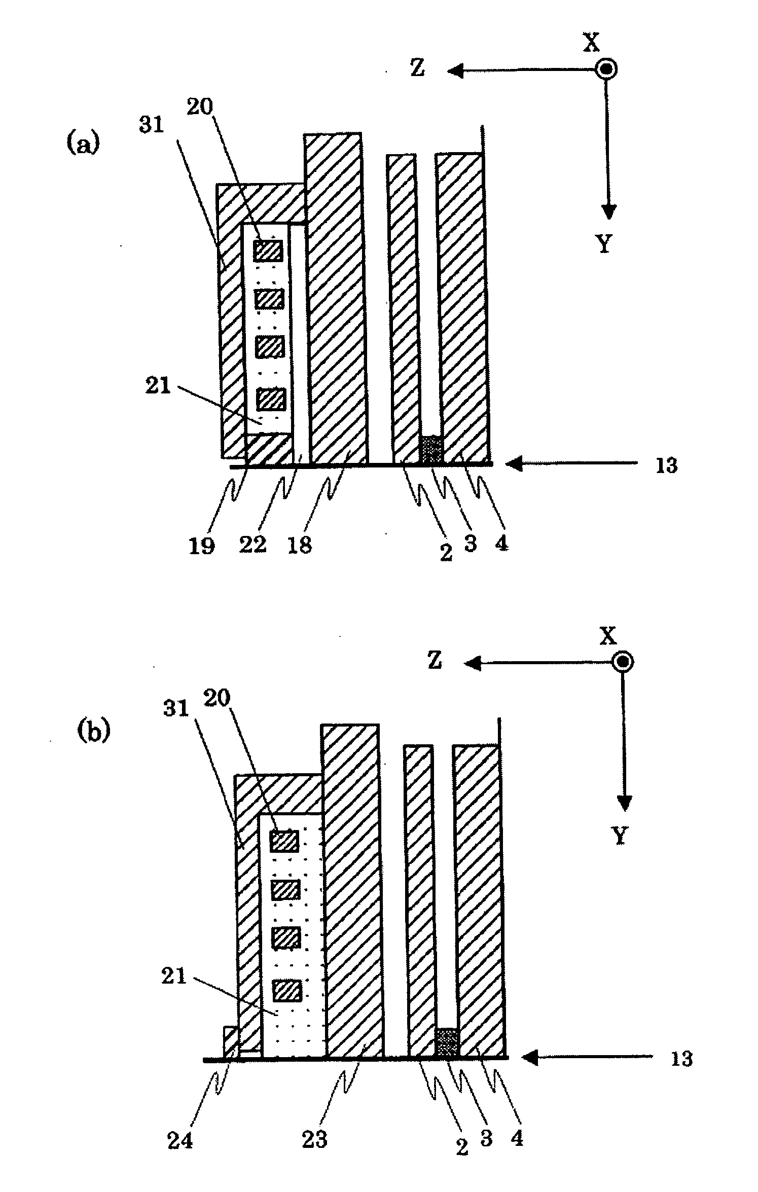
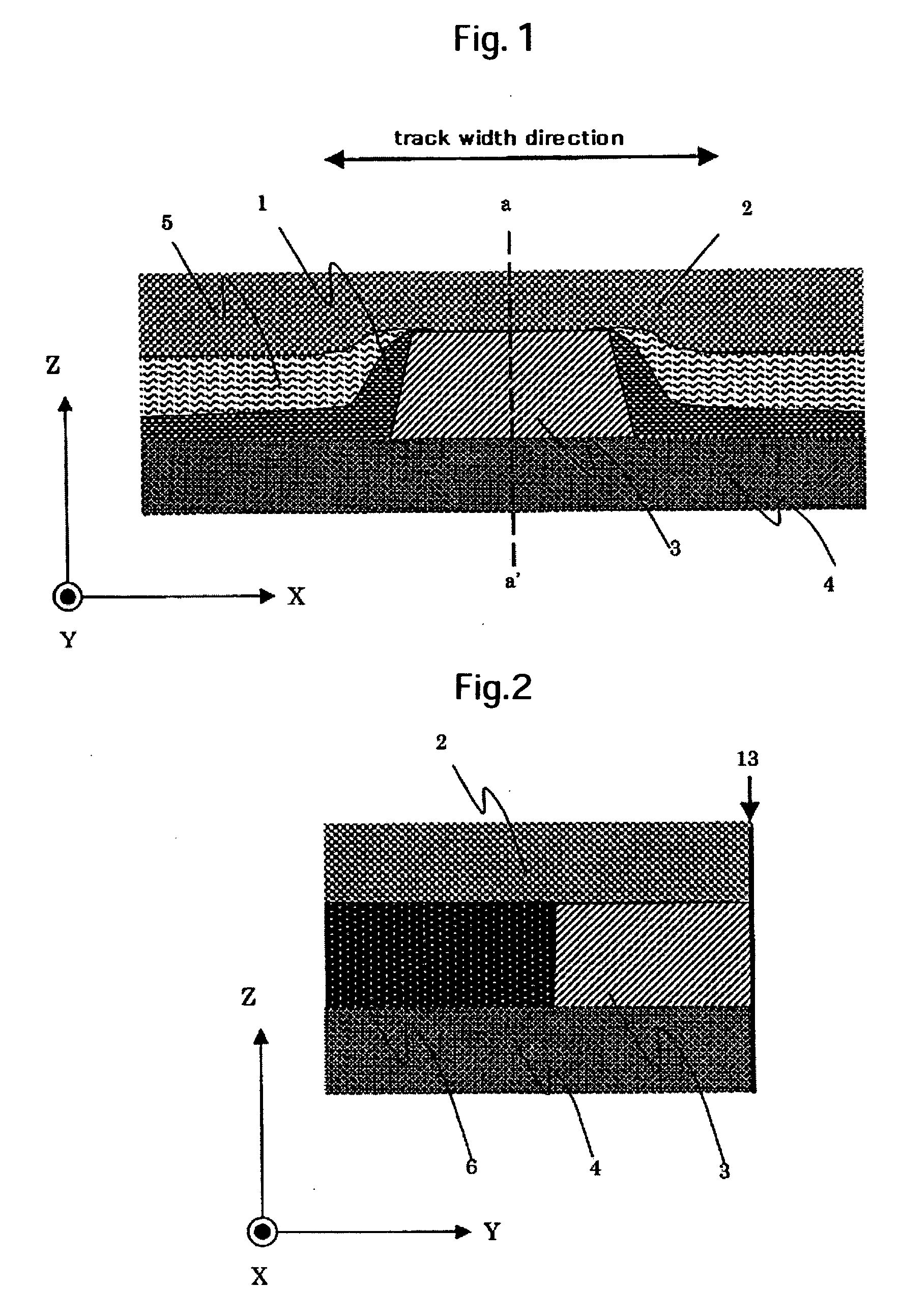
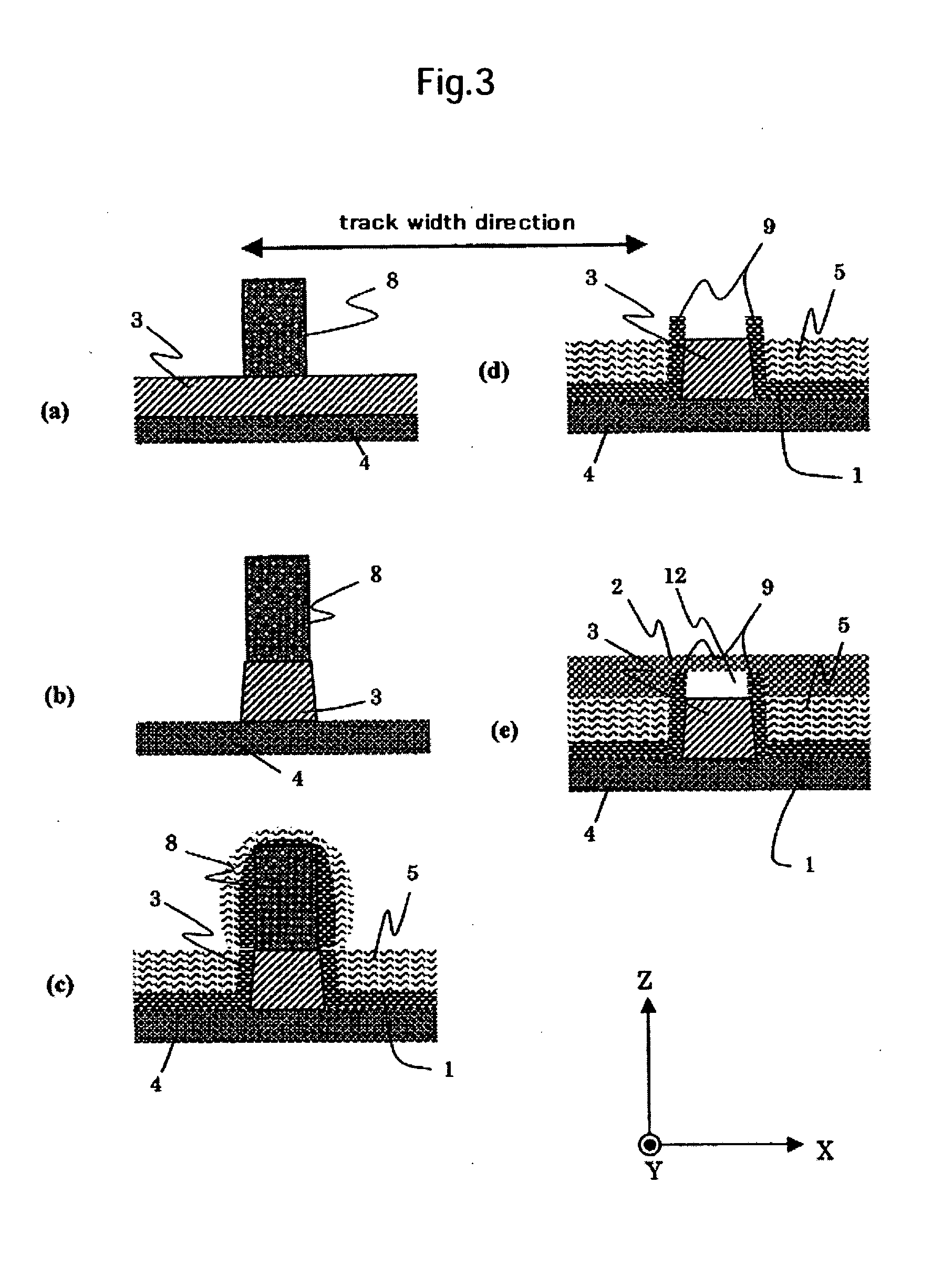
[0052] A method for fabricating a magneto-resistive sensor will be described as an example of the present invention usingFIGS. 7, 8, and 9. FIG. 7 is cross-sectional drawings in the sensor height direction at a position where a magnetoresistive film 3 is placed that shows the formation process in the sensor height direction. FIGS. 8 and 9 are cross-sectional drawings in the track width direction at a position where a magnetoresistive film 3 is placed that show the formation processes of the track. These embodiments are separated into the case when the first stopper layer for track 51 is removed (embodiment 1-1) and the case when it is not removed (embodiment 1-2) as will be explained later. FIG. 8 shows the process for forming the track described in the embodiment 1-1, and FIG. 9 shows the process for forming the track described in embodiment 1-2.

[0053] At first, an insulator such as Al2O3 etc. is deposited on the surface of a substrate composed of alumina titanium carbide, etc. an...

embodiment 2

[0076] The embodiment 1 described the case when the first stopper layer for sensor height 41 was not used during formation in the sensor height direction or when it was formed using DLC. However, in the case when it is necessary to make the length of the resist mask 11 smaller in the sensor height direction, a fabricating method described as follows becomes necessary. A method for fabricating a magneto-resistive sensor of this embodiment will be described with reference to the following drawings herein.

[0077] This embodiment can be divided into a total of four cases; the case when the first stopper layer for sensor height 41 is removed in the formation process of the sensor height, and the case when not removed; the case when the first stopper layer for track 51 is removed in the formation process of the track, and the case when not removed. Hereafter, the explanation will be carried out as follows; the case when both the first stopper layer for sensor height 41 and the first stopp...

embodiment 3

[0105] This embodiment is one in which the sensor height is formed after the formation of the track of the magnetoresistive film as shown in FIG. 6, and it is separated into the case when the first stopper layer for track 51 is removed (embodiment 3-1) and when it is not removed (embodiment 3-2) which will be described later during the track formation process. FIG. 20 shows the track formation process described in the embodiment 3-1, and FIG. 21 the track formation process described in the embodiment 3-2. FIG. 22 shows the sensor height formation process described in the embodiment 3-1, and FIG. 23 the sensor height formation process described in the embodiment 3-2.

[0106] The process for fabricating a magneto-resistive sensor of this embodiment will be described as follows. At first, an insulator such as Al2O3, etc. is deposited on the surface of a substrate composed of alumina titanium carbide, etc. and the lower shield layer 4 is formed after applying precision polishing using CM...


PUM


Abstract

A high output magneto-resistive sensor is provided by suppressing leftover resist mask after lift-off and generation of a fence, and by making it easy to remove the redepositions deposited on the side wall in the track width direction or on the side wall in the sensor height direction of the magnetoresistive film. As a means to solve a fence and lift-off leftover of a resist in a process for forming a track and a process for forming a sensor height, a stopper layer is provided on the magnetoresistive film and the stopper layer on the refill film, and performing lift-off by CMP. By using a metallic material which has a small CMP polishing rate for at least the first stopper layer, the magnetoresistive film and the first stopper layer can be etched simultaneously and a pattern formed. As a result, decrease of the height of the resist mask by RIE can be suppressed and lift-off leftover can be prevented.

Description

CROSS-REFERENCES TO RELATED APPLICATIONS [0001] This application claims priority from Japanese Patent Application No. JP2004-369118, filed Dec. 21, 2004, the entire disclosure of which is incorporated herein by reference. BACKGROUND OF THE INVENTION [0002] The present invention relates to a magneto-resistive sensor reproducing magnetically recorded information and a magnetic storage mounting it. Particularly, it relates to a magneto-resistive sensor having a high output and a fabricating method thereof, a magnetic head using it, and a magnetic storage mounting it. [0003] A magneto-resistive sensor utilizing a magnetoresistance, in which the electrical resistance changes according to changes in an external magnetic field, is well known as an excellent magnetic field sensor, and has been put to practical use as a read sensor for detecting a signal field from a magnetic recording medium which is a main part of a magnetic storage. [0004] The recording density of a magnetic storage has b...

Claims


Application Information

Patent Timeline
IPC IPC(8): G11B5/33G11B5/127
CPCG01R33/09G11B5/3163G11B5/3169G11B5/39
Inventor OSUGI, MASAHIROSHINTANI, TAKUWATANABE, KATSUROYOSHIDA, NOBUO
Owner WESTERN DIGITAL TECH INC
Learn More