
Thin thickness measurement method and apparatus

Active Publication Date: 2006-06-22
HONEYWELL INT INC
View PDF36 Cites 43 Cited by
  • Summary
  • Abstract
  • Description
  • Claims
  • Application Information

AI Technical Summary

Benefits of technology

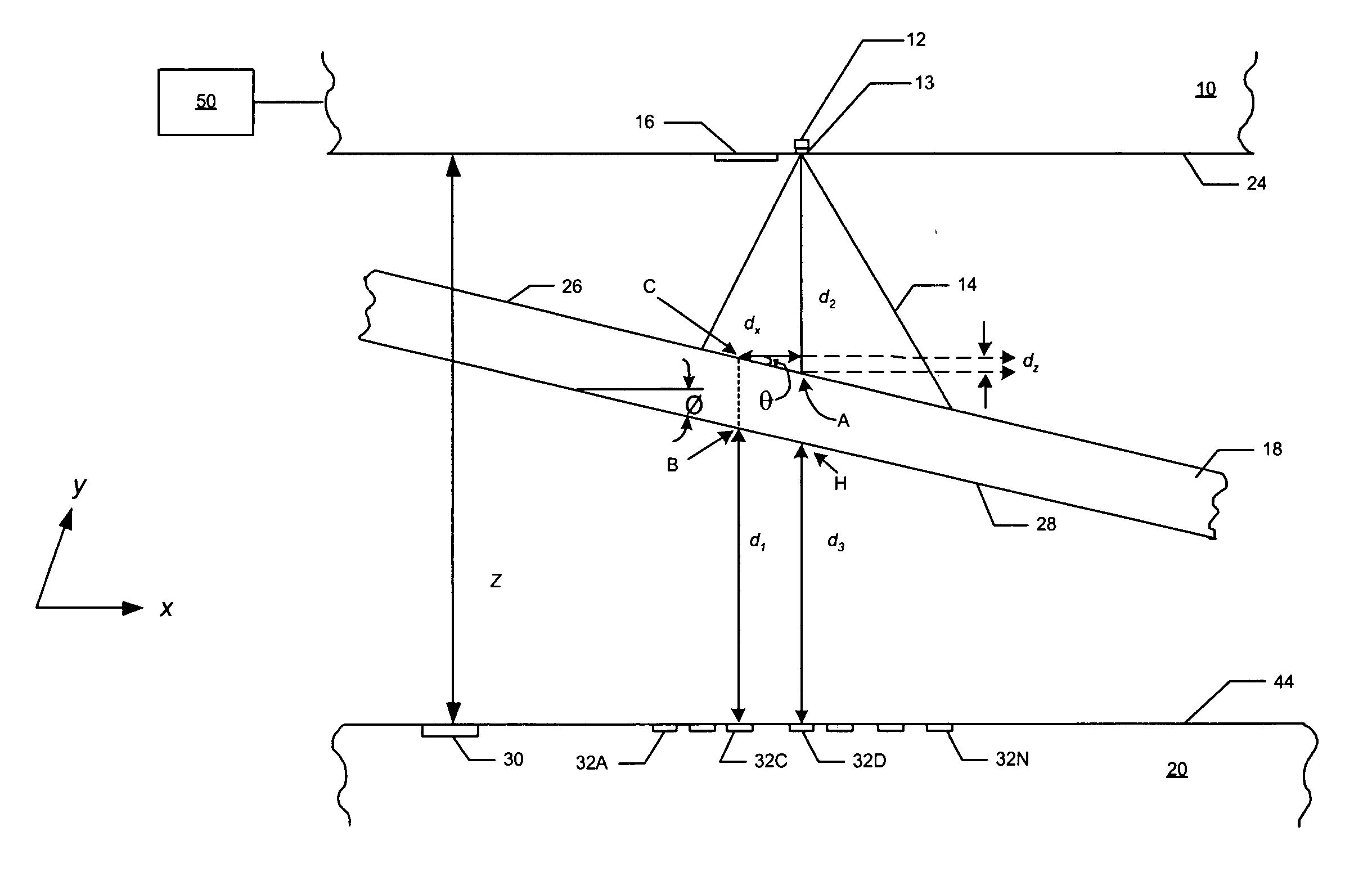
[0010] The present invention is based in part on the development of non-contact techniques for measuring the thickness of thin films especially traveling films that are less than one millimeter thick. The invention employs an optical sensor apparatus that has two sensor heads that are spaced apart to define a path through which the film is positioned. A pattern of known geometry is imaged onto a surface of the film and the image is analyzed with pattern recognition algorithm to determine the sensor head to film distance and the tilt of the film. Unlike prior art, the invention does not require extreme degrees of detection beam overlap to compensate for paper tilt, which is required for current approaches that employ single point laser distance measurements on both sides of paper

Problems solved by technology

Many variations and improvements to these methods exist, but each of the techniques has underlying drawbacks.
The contacting method is subject to three fundamental types of problems.
First, the method can be limited by the strength of the material being measured.
With fragile sheets such as tissue, for example, there is a tendency for the contacting shoes to snag deviations in the sheet surface, causing flaws in the sheet or even causing the sheet to tear.
Second, the sheet itself can damage a contacting caliper sensor due either to abrasive wear on the contacting elements or to physical damage arising during sheet breaks.
For caliper sensors that traverse the sheet, damage can also be caused when the sensor crosses the sheet edge.
Third, the accuracy of contacting sensors can be adversely affected by the buildup of contaminants on the contacting elements, as may occur with coated or filled sheets or sheets containing recycled materials.
The non-contacting inferential thickness measurement methods avoid many of the problems of the contacting methods, but are subject to a new set of problems.
Also the radioactive measurement is inferential, which means that if the density of the web is not as predicted, there may be significant errors in the calculated thickness value.
However, there are difficulties with previous non-contacting techniques that can limit their use to relatively low-accuracy situations.
One of the problems is that the web may not always be perpendicular to the incident light, since the web has a tendency to bounce or develop intermittent wave-like motion.
If the web is non-perpendicular to the incident light and the light beams from two opposing light sources are not directed to exactly the same spot on the sheet, substantial error in measurement can occur.
First, actual web thickness variations from the first laser's measurement spot to the second laser's measurement spot can cause an incorrect thickness measurement.
Second, if the web is not perpendicular to the incident light, the measurement technique will cause an error in the thickness value proportional to the web's angle and to the displacement on the sheet surface between the two measurement spots.
Bouncing or oscillation of the web can further exacerbate this error.
Another issue with the projection of laser light on to a paper or thin film is that the surface is usually not well defined and the paper or film is semi-transparent.
Current laser triangulation sensors which use position sensitive detector such as Lateral Effect Detectors (LEP), Quad-cell or Bi-cell detectors contain insufficient information that is needed to extract the ‘true’ surface location of the surface.
Various minute changes in system geometry caused, in part, by thermal effects on physical dimensions of the measurement apparatus or by device calibration, can also degrade the measurement accuracy.
These effects can be difficult to quantify directly, for example, by measuring temperatures at various points in the apparatus and applying appropriate correctors.
These adverse effects become substantially more significant as the accuracy level of the measurement device approaches that required for the measurement and control of products such as newsprint or other thin products.

Method used


Image

  • Thin thickness measurement method and apparatus
  • Thin thickness measurement method and apparatus
  • Thin thickness measurement method and apparatus

Examples


Embodiment Construction

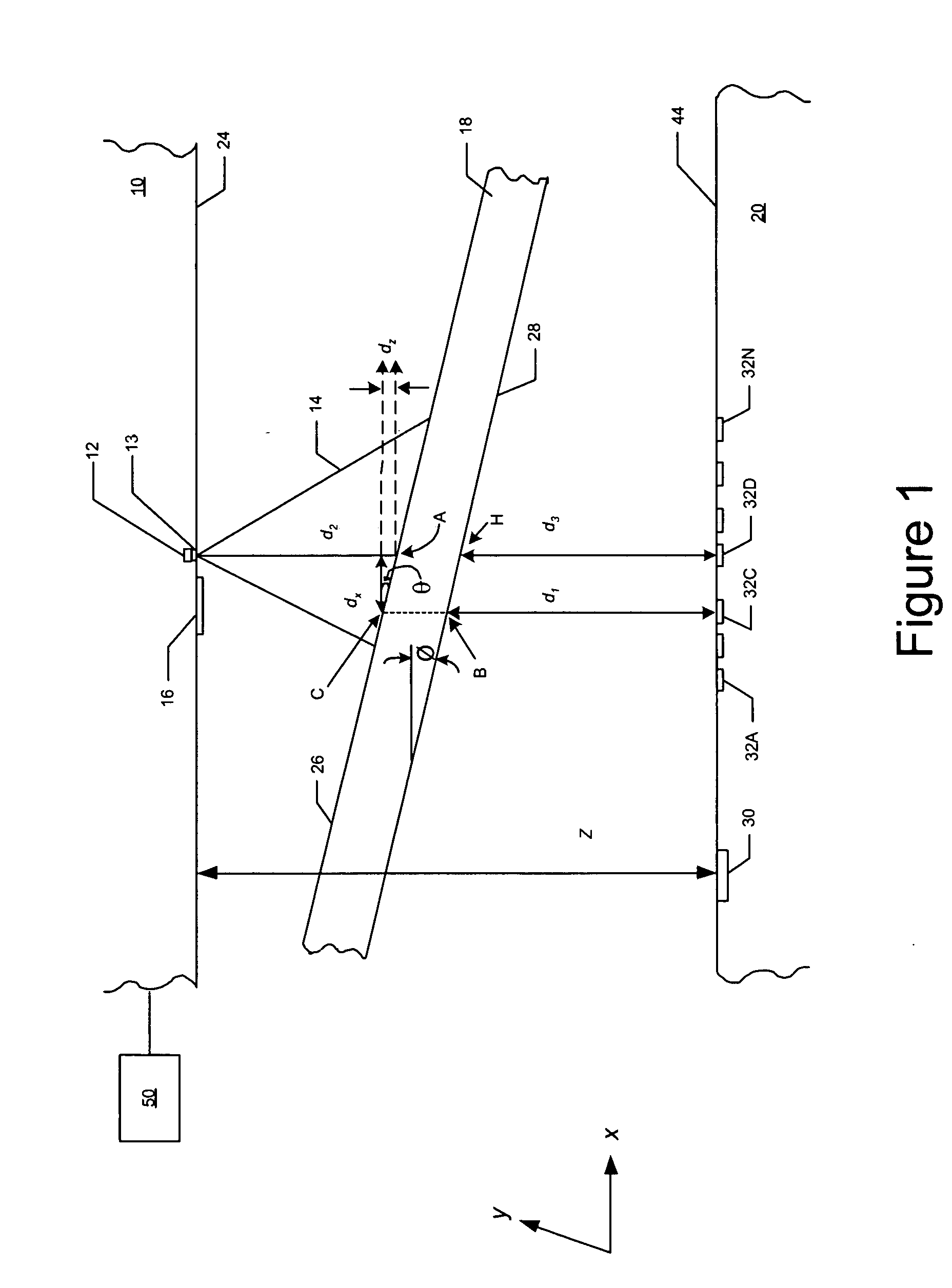
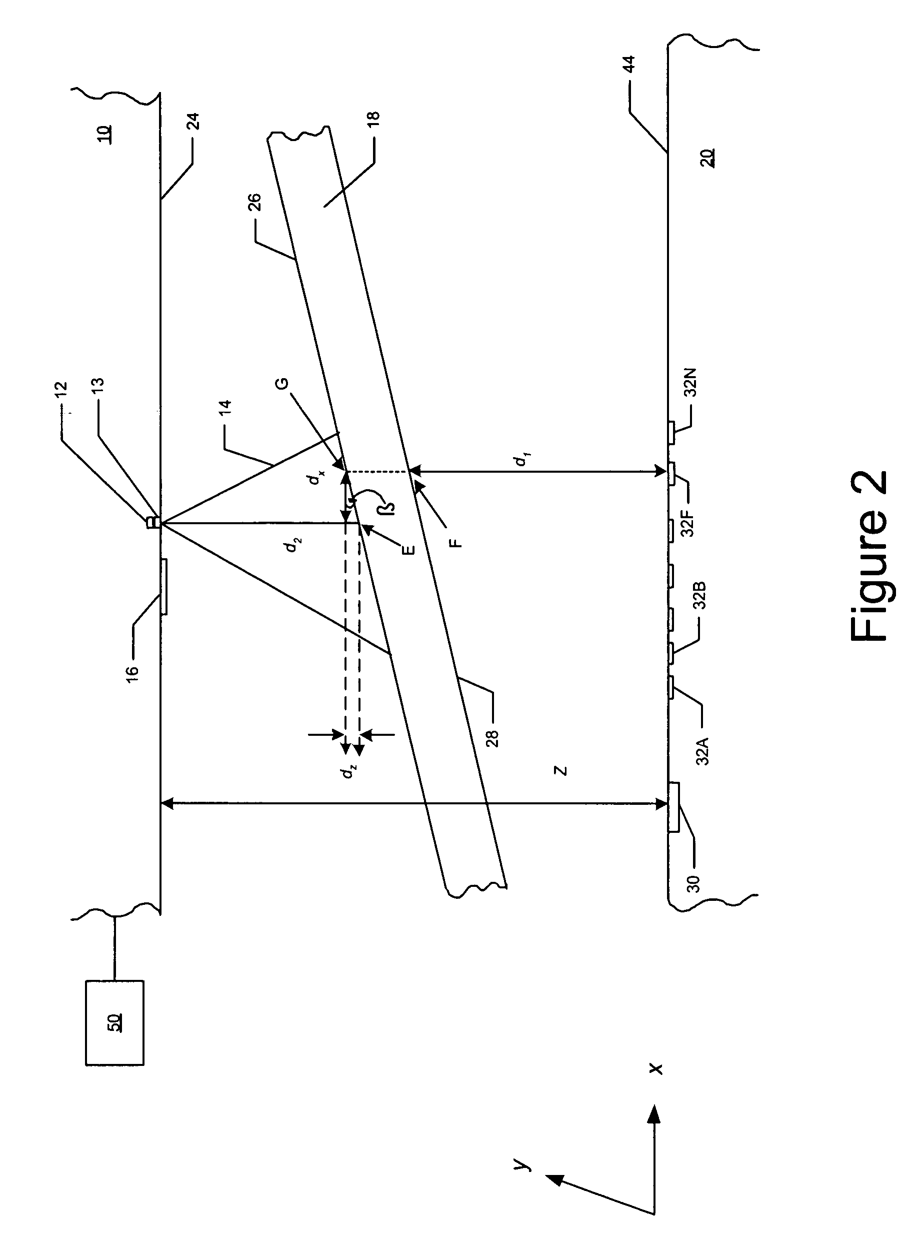
[0029] As shown in FIG. 1, a non-contact web or sheet thickness measurement device of the present invention includes first and second enclosures or heads 10 and 20, respectively, which are vertically spaced apart. Surface 24 and surface 44 are preferably parallel to each other and are separated from each other by a distance that is denoted Z. Each sensor head includes various optical sensors for measuring selected dimensions as further described herein. A web 18 that is positioned between the sensor heads moves linearly in the direction of the y-axis. Due to the difficulty of mechanically constraining the moving web, the web 18 does not necessarily move along in a straight line that is parallel to the planar surfaces 24, 44. In this example, the web 18 is tilted; the angle between the upper or first surface 26 of the web 18 and the x-axis is denoted θ. Generally the top and bottom planar surfaces of the web are parallel to each other so that the angle θ made with the top surface is ...


PUM


Abstract

Techniques for non-contacting thickness or caliper measurements of moving webs or sheets employ a sensor device that includes a first sensor head and a second sensor head that are spaced apart to define a path through which the moving web travels. The sensor device projects a laser generated, multiple points pattern onto the upper surface of the moving web. Pattern recognition algorithm analysis of the pattern identifies the orientation, e.g., tilt, of the moving web. The device further measures the film tilt, the distance between the first sensor head and the first web surface, the distance between the second sensor head and the second web surface, and the distance between the two sensor heads to provide a highly accurate on-line thickness measurement of the moving web.

Description

FIELD OF THE INVENTION [0001] The present invention relates generally to techniques for non-contacting thickness or caliper measurements, and more particularly to a device that projects a laser generated, multiple points pattern onto the upper surface of a film which is moving along a path between two sensor heads that are vertically spaced apart. The device measures the film tilt, the distance between upper sensor head and the upper film surface, the distance between the lower sensor head and the lower film surface, and the distance between the two sensor heads to determine the thickness of the moving web. BACKGROUND OF THE INVENTION [0002] Numerous methods exist for measuring the thickness of a moving web or sheet, such as paper. Two of the most common techniques include a direct thickness measurement using contacting glides or shoes, which skim along the two surfaces of the web, and a non-contacting inferential method in which radiation absorption by the web is used to determine ...

Claims


Application Information

Patent Timeline
IPC IPC(8): G01B11/06G01N21/84
CPCG01B11/0691
Inventor JASINSKI, W. TEDHARAN, FRANK M.
Owner HONEYWELL INT INC
Learn More