
Cursor motion control of a pointing device

Active Publication Date: 2006-06-22
PIXART IMAGING INC
View PDF10 Cites 17 Cited by
  • Summary
  • Abstract
  • Description
  • Claims
  • Application Information

AI Technical Summary

Benefits of technology

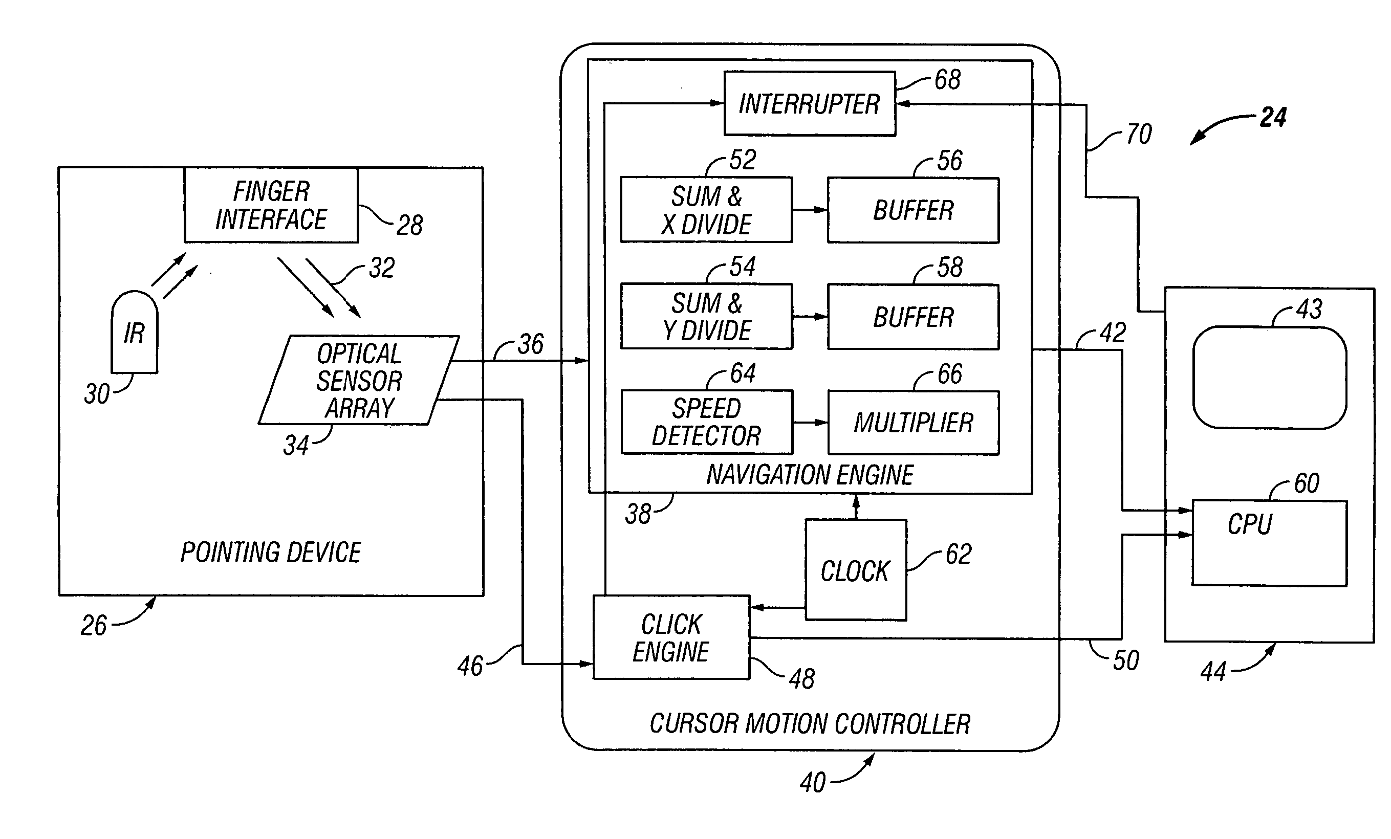
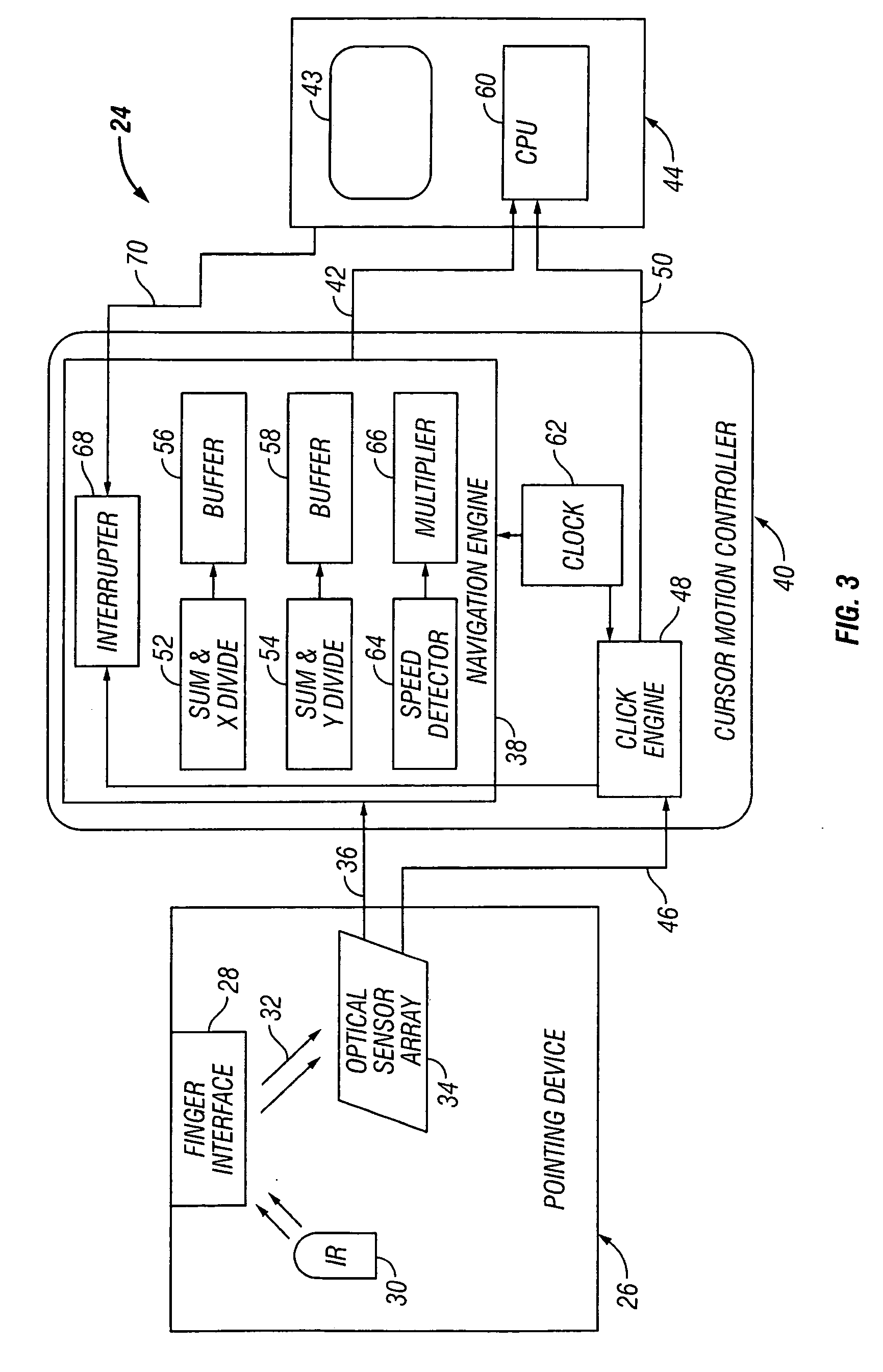
[0007] A system is provided for controlling the motion of a cursor on a display of an electronic apparatus. A pointing device generates pixel counts at a predetermined frame rate indicative of motion in predetermined axes of a user's digit across an imaging surface. A cursor motion controller receives the pixel counts and generates navigation output signals representing averages over predetermined time intervals selected to smooth the motion of a cursor on the display of the hand held electronic apparatus. Optionally the cursor motion controller

Problems solved by technology

Small track balls, drag pads, and strain sensing sticks have been used on lap top computers since they are often used in environments where a drag surface for a mouse is not available and it is impractical to have a cord connecting the lap top to the pointing device.
It has been discovered that a pointing device that relies on the motion of a digit across an imaging surface can produce annoying inaccuracies due to jagged and / or non-uniform cursor movement.
This drawback is similar to that encountered with drag pads incorporated into lap top computers.
Still another shortcoming of a pointing device that relies on the motion of a digit across an imaging surface is that it is sometimes difficult to make the transition between cursor movement and action selection, for example at a menu or URL link.
A finger lift-up motion followed by a finger put-down motion to accomplish a click can lead to spurious cursor motion and ineffective user commands.

Method used


Image

  • Cursor motion control of a pointing device
  • Cursor motion control of a pointing device
  • Cursor motion control of a pointing device

Examples


Embodiment Construction

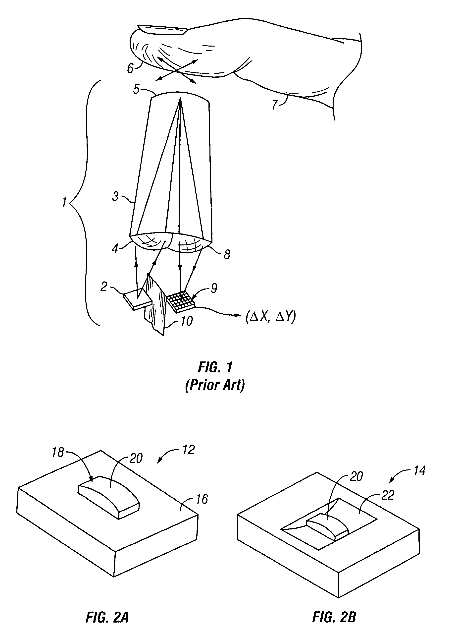
[0014]FIG. 1 illustrates a prior art pointing device 1 that relies on the motion of a digit across an imaging surface to move a cursor on a display, details of which may be found in the aforementioned U.S. Pat. No. 6,057,540 of Gordon et al. The tip 6 of a finger 7 is pressed against the distal end or imaging surface 5 of a transparent plastic stud that forms a rod lens 3. An infrared LED light source 2 emits light that is gathered and focused by a lens 4 on the proximal end of the rod lens 3. Ridges and other surface features on the finger tip 6 are illuminated by the light conveyed through the rod lens 3. An array of photo detectors in a movement sensor 9 adjacent the proximal end of the rod lens 3 receives light reflected from the finger tip 6 which is focused on the detectors by another lens 8 also on the proximal end of the rod lens 3. The movement sensor 9 generates pixelized representations comprising a reference array and shifted versions thereof that are used to produce del...


PUM


Abstract

A pointing device generates pixel counts at a predetermined frame rate indicative of motion in predetermined axes of a user's digit across an imaging surface. A cursor motion controller receives the pixel counts and generates navigation output signals representing averages over predetermined time intervals selected to smooth the motion of a cursor on the display of an electronic apparatus. Optionally, the cursor motion controller can multiply a pixel count in each frame by a predetermined acceleration factor so that a cursor on the display of an electronic apparatus will move a greater distance based on an increased rate of motion of the user's digit across the imaging surface. Optionally, the cursor motion controller can interrupt the generation of navigation output signals for a predetermined interrupt period after completion of a cursor stroke. The averaging, acceleration and interruption features can be used independently or in various combinations.

Description

BACKGROUND OF THE INVENTION [0001] The use of hand operated pointing devices to control the position of a cursor on a computer display has become extremely widespread. The most popular of such navigation devices is the mouse. Recently, in computer mouses being commercialized in the United States, the mechanical ball that partially protrudes through the underside of the mouse has been replaced with an optical laser tracking device to avoid failures due to lint build-up and mechanical wear associated with the ball. See U.S. Pat. No. 6,281,882 granted Aug. 28, 2001 to Gordon et al., assigned to Agilent Technologies, Inc., and entitled PROXIMITY DETECTOR FOR A SEEING EYE MOUSE. [0002] Small track balls, drag pads, and strain sensing sticks have been used on lap top computers since they are often used in environments where a drag surface for a mouse is not available and it is impractical to have a cord connecting the lap top to the pointing device. In so-called personal digital assistant...

Claims


Application Information

Patent Timeline
IPC IPC(8): G09G5/08
CPCG06F3/0317
Inventor MACHIDA, AKIHIRO
Owner PIXART IMAGING INC
Learn More