
Bed side rail method and apparatus

Inactive Publication Date: 2006-06-22
SMITH ROBYN
View PDF8 Cites 28 Cited by
  • Summary
  • Abstract
  • Description
  • Claims
  • Application Information

AI Technical Summary

Benefits of technology

[0012] The apparatus described below provides a safer alternative to the prior art departing from the teachings thereof and providing the swing-free mode without lateral entrapment zones. The apparatus is fixed at the right and / or left corners of the bed frame with a vertical bar that slides in and out of an attached sleeve. The bar is height adjustable, fixed at the position lengthwise to the bed, but freely swinging away from the bed to 90 degrees (in one form) intentionally pushed away by a caregiver or when a patient crawls off the side of the bed. This unfixed swing-free mode prevents entrapment between the rail and the mattress portions of the bed.
[0013] Individuals with cognitive impairment can grasp the bar when a caregiver directs them to hold the bar during turning and repositioning in bed. The system acts as a second caregiver in that it provides a means for the individual to exert their weight to the bar, thus saving a caregiver from using their body and averting the harm caused by back, neck and shoulder strain.
[0014] Individuals are able to participate in the repositioning and sitting up at the edge of bed as independent as possible which enhances their self image, range of motion activity and flexibility in the joints involved with bed mobility, transferring and standing. Further, facilities reap the potential financial benefit of decreased work related injury claims from less staff injuries. Facilities also potentially reap financial benefits in less State or Federal Citations for residents not achieving their highest level of physical function and they can experience less injuries in mentally impaired clients from entrapment in side rails. Such a system as described below can further satisfied family members as their loved ones improve.

Problems solved by technology

In certain cases, the individual may be somewhat cognitively impaired such as in the case with an elderly patient suffering from dementia.
With any form of cognitive impairment or even certain physical disabilities, there is a risk that the individual may fall off the lateral portion of the bed.
If the individual is inadvertently pinched or stuck between any kind of support member, the individual may suffer severe injury or even death by way of suffocation.
These entrapment issues are potentially lethal and many individuals do not have around the clock supervision and of course have a certain amount of privacy while in bed.
Further, when an individual is in a trap position they may not have the mental or physical ability to call for help or press any type help call indicator to alert the nurse or caregiver.
With the increased risk of injury and death reported to the FDA by patients crawling over, through and around the prior art “side rails”, in their traditional position, have become safety risks for clients with fragile physical body frames, and / or those with mental deficits such as seen in dementia.
As a further note, historically, certain issues have occurred with beds that articulate.
The FDA has recognized that articulation of the bed introduces complex geometries that make applying dimensional criteria to reduce entrapment difficult.
And like turn, in articulation of a bed (where the head portion raises about a longitudinal pivot axis along the medial region of the bed) such movement can create an additional array of issues with respect to potential entrapment of the bed occupant.

Method used


Image

  • Bed side rail method and apparatus
  • Bed side rail method and apparatus
  • Bed side rail method and apparatus

Examples


Embodiment Construction

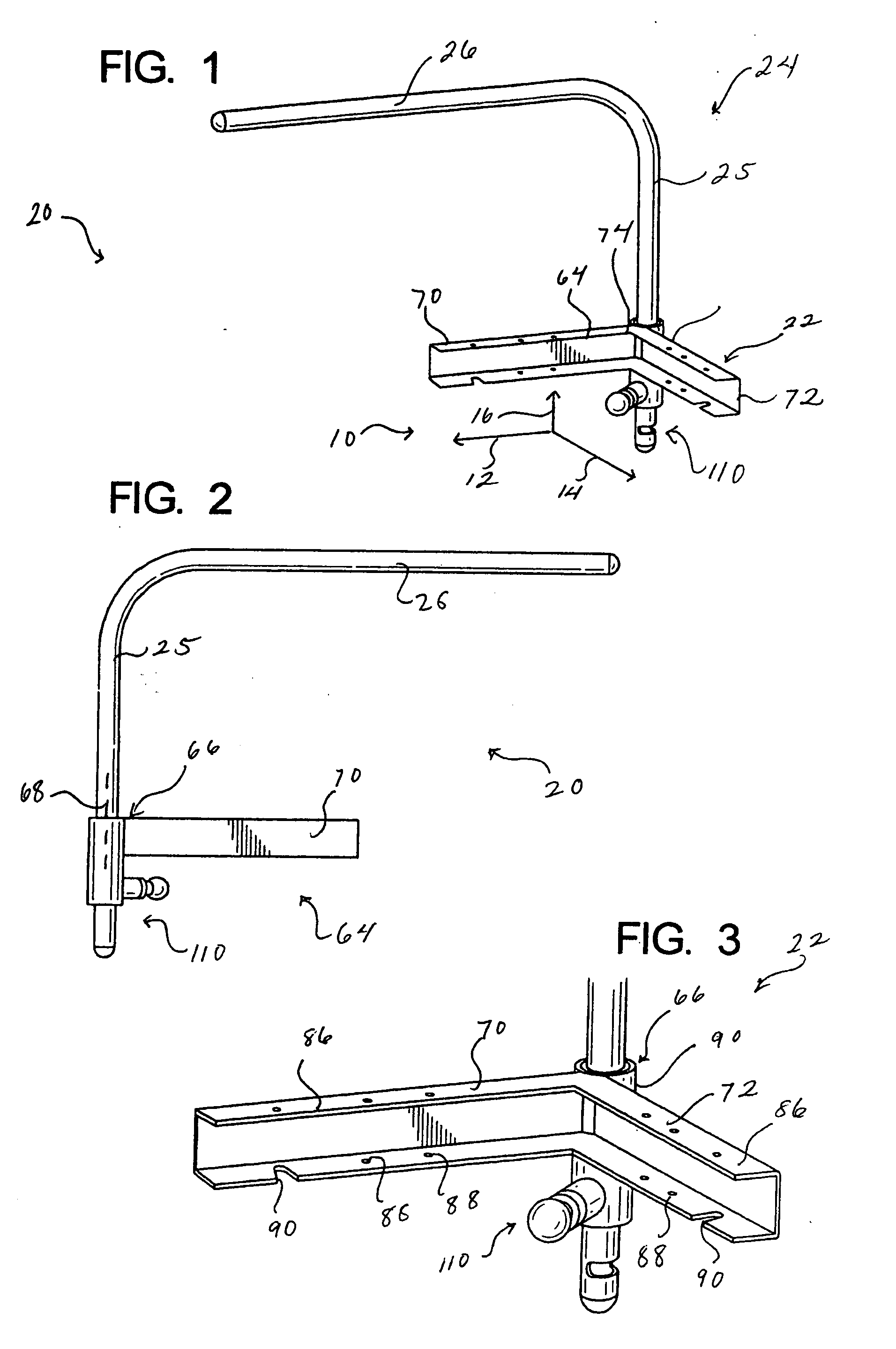
[0034] As shown in FIG. 1, the bedside support device 20 is shown in an isometric view in an assembled state not attached to a bed. To aid in the description, an axes system 10 is defined where the axis 12 indicates a longitudinal axis and the axis 14 indicates a lateral axis. Further, the axis substantially orthogonal to 12 and 14 is a vertical axis indicated at 16. The arrow indicating the lateral axis 14 points in a laterally inward direction where inward and outward are generally referenced from a longitudinal center region of the bed. The axis system is utilized to aid in the description of the various moving parts and orientation of components for a general direction and is not intended to limit the directional vectors to the exact orthogonal relationships shown in FIG. 1.

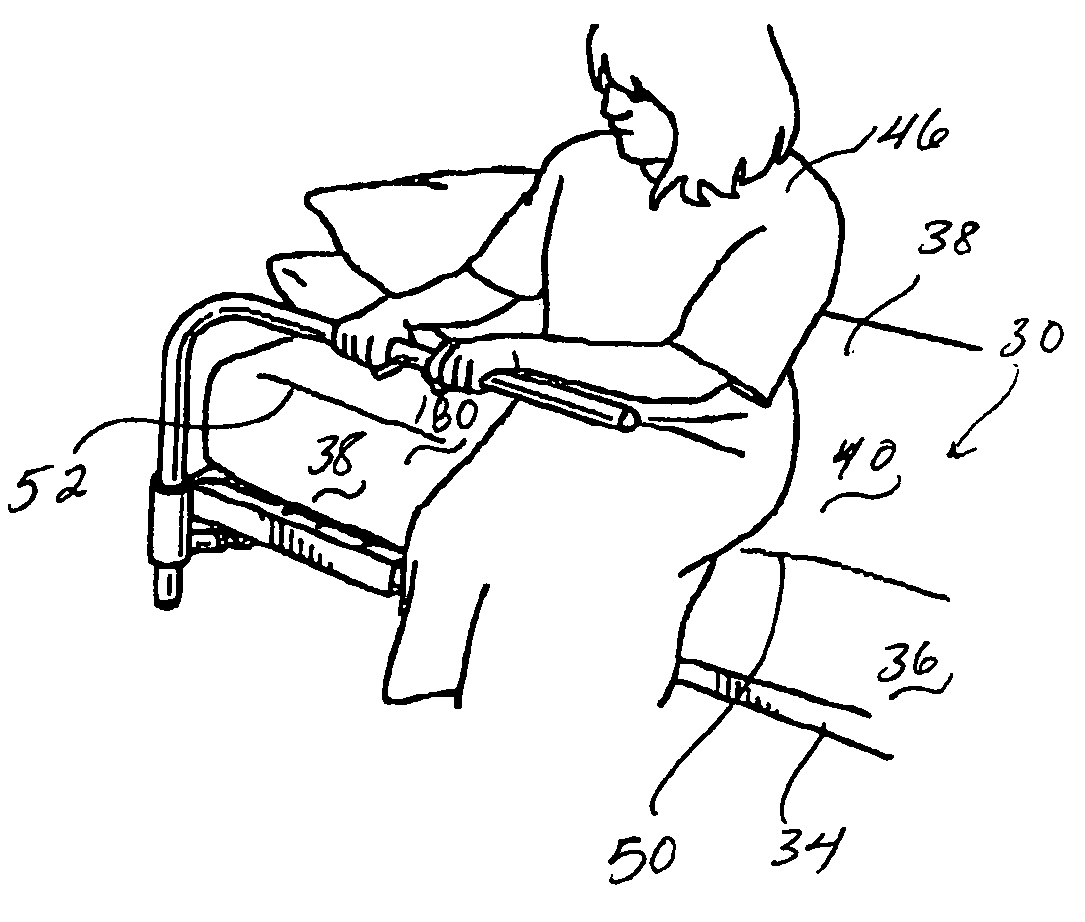
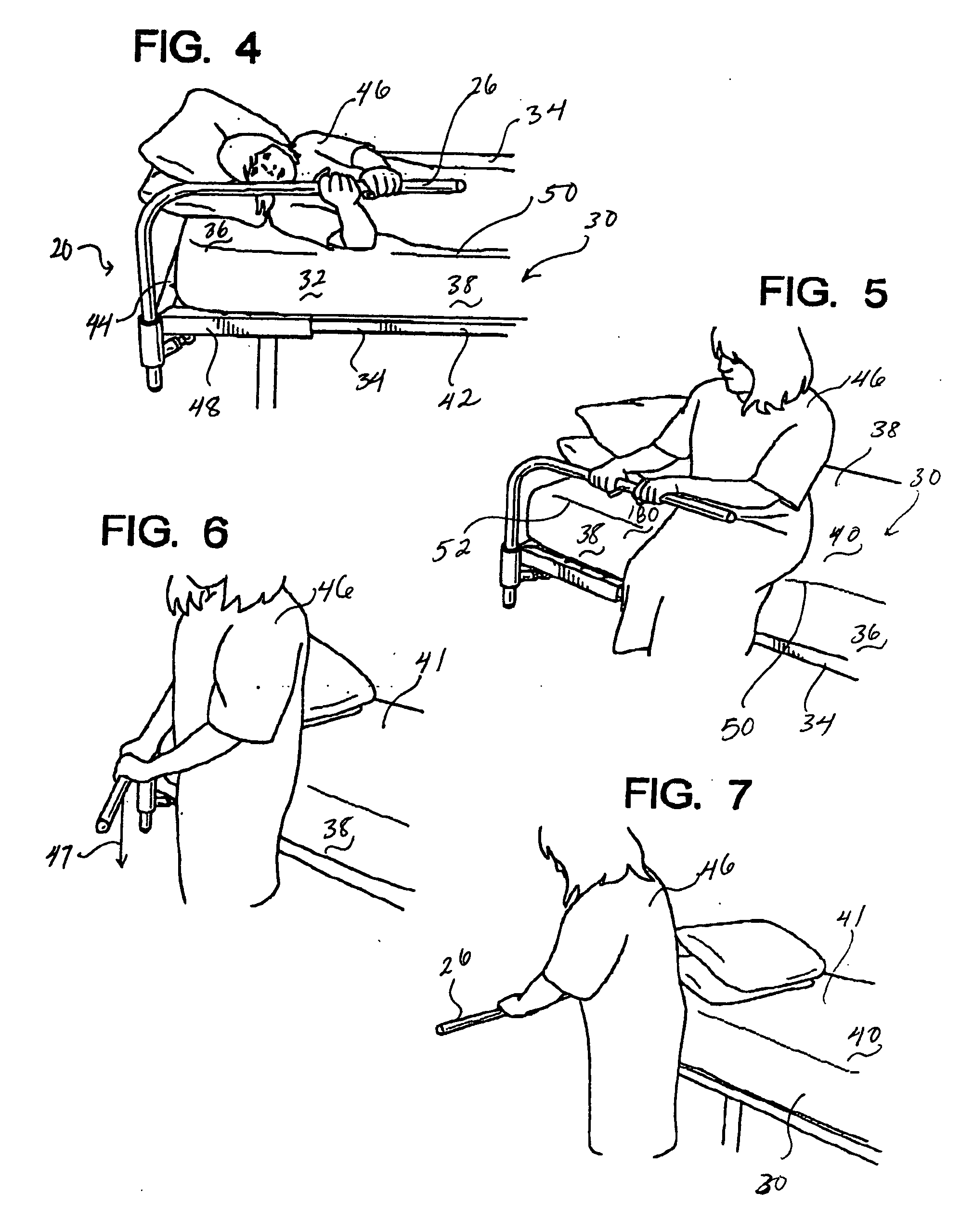
[0035] Briefly referring ahead now to FIG. 4 there will be a discussion of the overall environment of the bedside support device 20. As shown in FIGS. 4-7, the bedside support device 20 is adapted to be moun...


PUM


Abstract

A bedside support device having a free swinging mode of a handle member where the handle member is positioned in a manner to prevent entrapment zones while in a free swinging mode to prevent injury to the individual in requirement of support. The bedside support device is adapted to resist vertical force placed thereon to give vertical support to an individual while allowing the handle region to reposition laterally to allow the individual to move to and from the bed structure. The handle region defined an unobstructed side region to allow the individual's legs to be placed under the handle member to properly allow the individual to stand up or sit down on the bed structure in a controlled and safe manner.

Description

RELATED APPLICATIONS [0001] This application claims priority benefit of U.S. Ser. No. 60 / 588,678, filed Jul. 16, 2004.BACKGROUND OF THE INVENTION [0002] As our population ages and individuals are subjected to trauma, limiting their mobility, there is an ever-present need for providing individuals with a certain amount of mobility support in their daily living. A good portion of our lives is spent resting and such time is often spent in our bed either sleeping or perhaps bedridden due to an injury or illness. [0003] To aid individuals in need, various types of rails have been in production offering some form of assistance or containment within a bed in the home as well as in medical institutions such as hospitals. [0004] It is important to understand the dynamics of providing assistance to individuals in need of support getting in and out of bed. In certain cases, the individual may be somewhat cognitively impaired such as in the case with an elderly patient suffering from dementia. ...

Claims


Application Information

Patent Timeline
IPC IPC(8): A61G7/053A47C31/00
CPCA61G7/053
Inventor SMITH, ROBYN
Owner SMITH ROBYN
Learn More