
Model-based synthesis of band moire images for authentication purposes

a band moire image and image synthesis technology, applied in the field of anticounterfeiting and authentication methods and devices, can solve the problems of affecting the smooth dislocation and possible transformation of the revealed latent image, increasing the cost of produced documents or goods, and increasing the cost of documents such as banknotes

Active Publication Date: 2006-06-15
ECOLE POLYTECHNIQUE FEDERALE DE LAUSANNE (EPFL)
View PDF19 Cites 29 Cited by
  • Summary
  • Abstract
  • Description
  • Claims
  • Application Information

AI Technical Summary

Benefits of technology

The present invention relates to a system for protecting devices such as banknotes, checks, and passports from counterfeiting attempts. The invention uses a band moiré image layout model to predict the layout of the security document and its corresponding authentication means. The system also allows for the synthesis and delivery of the security document, as well as the individualization of the document for different users or classes of documents. The band moiré image layout model is sensitive to any microscopic variations in the base and revealing layers, making it difficult for counterfeiters to replicate the document. The invention offers an additional protection by allowing for the production of individual layouts for individual or groups of security documents.

Problems solved by technology

Counterfeiting of documents such as banknotes is becoming now more than ever a serious problem, due to the availability of high-quality and low-priced color photocopiers and desktop publishing systems.
Some of these means are clearly visible to the naked eye and are intended for the general public, while other means are hidden and only detectable by the competent authorities, or by automatic devices.
Nevertheless, there is still an urgent need to introduce further security elements, which do not considerably increase the cost of the produced documents or goods.
A second limitation of this technique resides in the fact that there is no enlargement effect: the pattern image revealed by the superposition of the base layer and of the revealing transparency has the same size as the latent pattern image.
Phase based modulation techniques allowing to hide latent images within a base layer are not capable of smoothly displacing and possibly transforming the revealed latent image when moving the revealing layer on top of the base layer.
For example, they are unable to create a continuous displacement of the band moiré image patterns, such as for example the band moiré image patterns moving towards the center of a circular band moiré image layout.
This last disclosure has the disadvantage of being limited to the case where the superposed revealing structure is a microlens array and the periodic structure on the document is a constant 2D array of identical dot-shapes replicated horizontally and vertically.
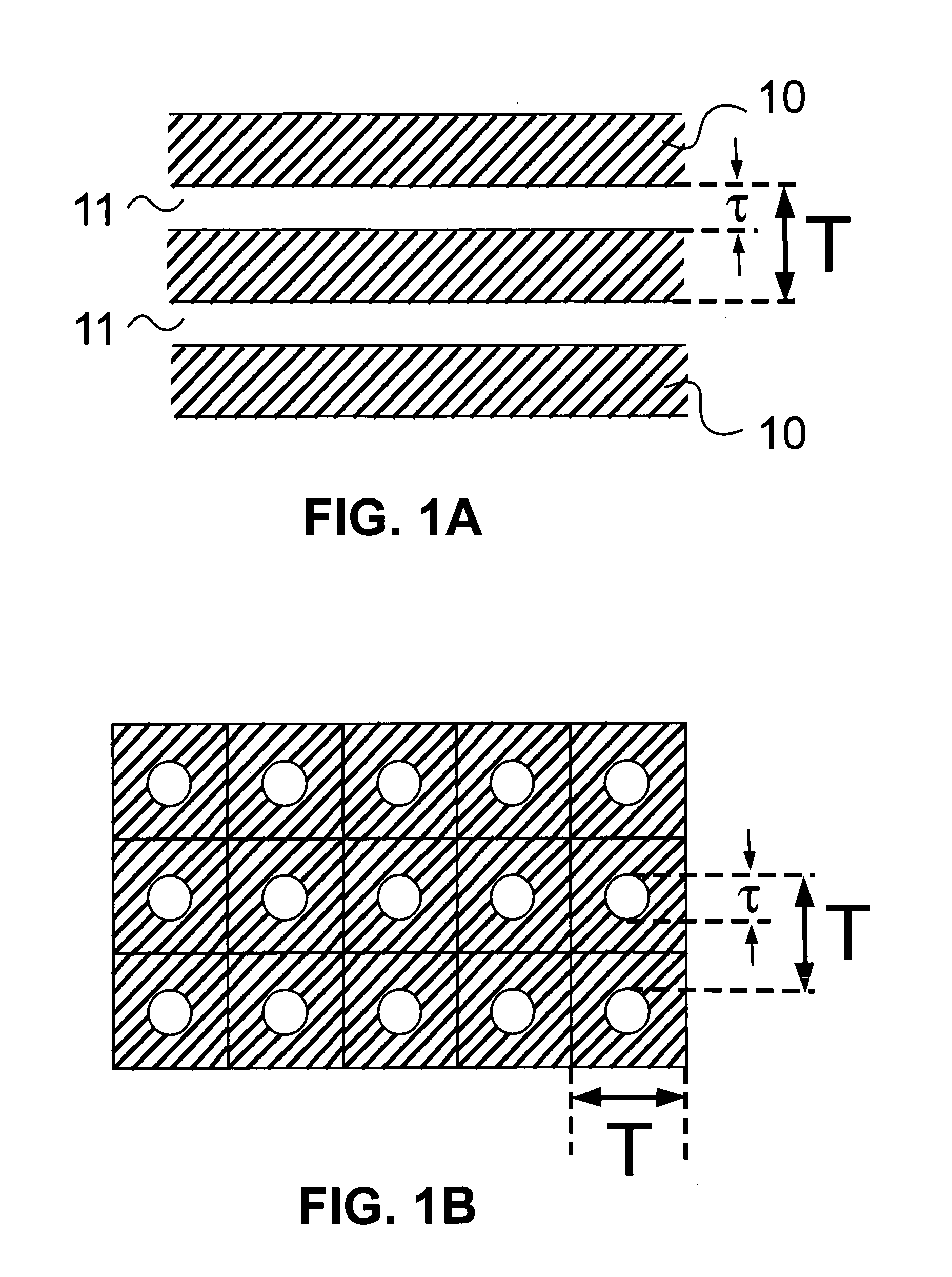
The first limitation is due to the fact that the revealing layer is made of dot screens, i.e. of a set (2D array) of tiny dots laid out on a 2D surface.
When dot screens are embodied by an opaque layer with tiny transparent dots or holes (e.g. a film with small transparent dots), only a limited amount of light is able to traverse the dot screen and the resulting moiré intensity profile is not easily visible.
The second limitation is due to the fact that the base layer is made of a two-dimensional array of similar dots (dot screen) where each dot has a very limited space within which only a few tiny shapes such as a few typographic characters or a single logo must be placed.
Furthermore, since it does not disclose a model for predicting the layout of the moiré image that can be produced when superposing a curvilinear base layer and a curvilinear revealing layer, band moirés image relying on curvilinear base or revealing layers need to be generated by a trial and error procedure.
When one of the layers layout is curvilinear, this trial and error method does not allow to compute a base band grating layer layout given a reference band moiré image layout and a revealing line grating layout.
In addition, since the method relies on trial and error, it does not support the derivation of complicated geometric transformations, such as computing a base layer, which in superposition with a revealing layer forming a spiral shaped line grating yields a meaningful, visually pleasant band moiré image.
Furthermore, U.S. patent application Ser. No. 10 / 270,546 (Hersch and Chosson) does neither give a precise technique for generating a reference rectilinear band moiré image layout with curvilinear base and revealing layer layouts nor does it give a means of generating a desired reference curvilinear band moiré image layout with a predetermined rectilinear or curvilinear revealing layer layout.
In addition, he didn't consider applying band moiré images for document authentication.
This makes it practically impossible for potential counterfeiters to resynthesize a base layer without knowing in detail the relevant geometric transformations as well as the constants used to synthesize the authentic base layer.

Method used


Image

  • Model-based synthesis of band moire images for authentication purposes
  • Model-based synthesis of band moire images for authentication purposes
  • Model-based synthesis of band moire images for authentication purposes

Examples


example a

Rectilinear Moiré Image and a Cosinusoidal Revealing Layer

[0153] In order to generate a rectilinear moiré image with a cosinusoidal revealing layer, we transform the original base and revealing layer shown in FIGS. 12A and 12B. We want the superposition of the transformed base and revealing layer to yield the same rectilinear moiré image (FIG. 19C) as the moiré image formed by the original rectilinear layers (FIG. 12C), i.e. m1(xt,yt)=xt and m2(xt,yt)=yt. We define the revealing layer transformation

g2(xt,yt)=yt+c1 cos (2 π(xt+c3) / c2)   (25)

with c1, c2 and c3 representing constants and deduce from equations (21) the geometric transformation to be applied to the base layer, i.e.

h1(xt,yt)=xt+c1 cos (2 π(xt+c3) / c2) (tx / Tr)

h2(xt,yt)=yt+c1 cos (2 π(xt+c3) / c2) (tyTr)   (26)

[0154] We can move the revealing layer (FIG. 19B) up and down on top of the base layer (FIG. 19A), and the moiré image shapes (FIG. 19C) will simply be translated (FIG. 19D) without incurring deformations. We can ...

example b

Rectilinear Moiré Image and a Circular Revealing Layer

[0155] We introduce a revealing layer transformation yielding a perfectly circular revealing line grating (FIG. 20B)

g2(xt,yt)=c1√{square root over ((xt−cx)2+(yt−cy)2)}  (28)

where cx and cy are constants giving the center of the circular grating and c1 is a scaling constant. In order to obtain a rectilinear moiré image, we define the base layer transformations according to Eq. 24 h1⁡(xt,yt)=xt+(c1⁢(xt-cx)2+(yt-cy)2-yt)·txTr⁢⁢h2⁡(xt,yt)=c1⁢(xt-cx)2+(yt-cy)2·tyTr+yt·Tr-tyTr(29)

The resulting base layer is shown in FIG. 20A. FIG. 20C, shows that the superposition of a strongly curved base band grating and of a perfectly circular revealing line grating yields the original rectilinear moiré image. However, as shown in FIG. 20D, a small displacement of the revealing layer, or equivalently a small relative displacement of the position sampled by the revealing layer on the base layer yields a clearly visible deformation (i.e. distort...

example c

Circular Band Moiré Image and Rectilinear Revealing Layer

[0157] In the present example, we choose a circular moiré image and also freely choose the revealing layer layout. The desired reference circular moiré image layout is given by the transformation mapping from transformed moiré space back into the original moiré space, i.e. x=m1⁡(xt,yt)=π-a⁢ ⁢tan⁡(yt-cy,xt-cx)2·π·wx⁢⁢y=m2⁡(xt,yt)=cm⁢(xt-cx)2+(yt-cy)2(30)

where constant cm expresses a scaling factor, constants cx and cy give the center of the circular moiré image layout in the transformed moiré space, wx expresses the width of the original rectilinear reference band moiré image and function atan(y,x) returns the angle α of a radial line of slope y / x, with the returned angle α in the range (−π2(xt,yt)=yt. This rectilinear revealing layer is shown in FIG. 22B. By inserting the curvilinear moiré image layout equations (30) and the curvilinear revealing layer layout equation g2(xt,yt)=yt into the band moire layout model equations ...


PUM


Abstract

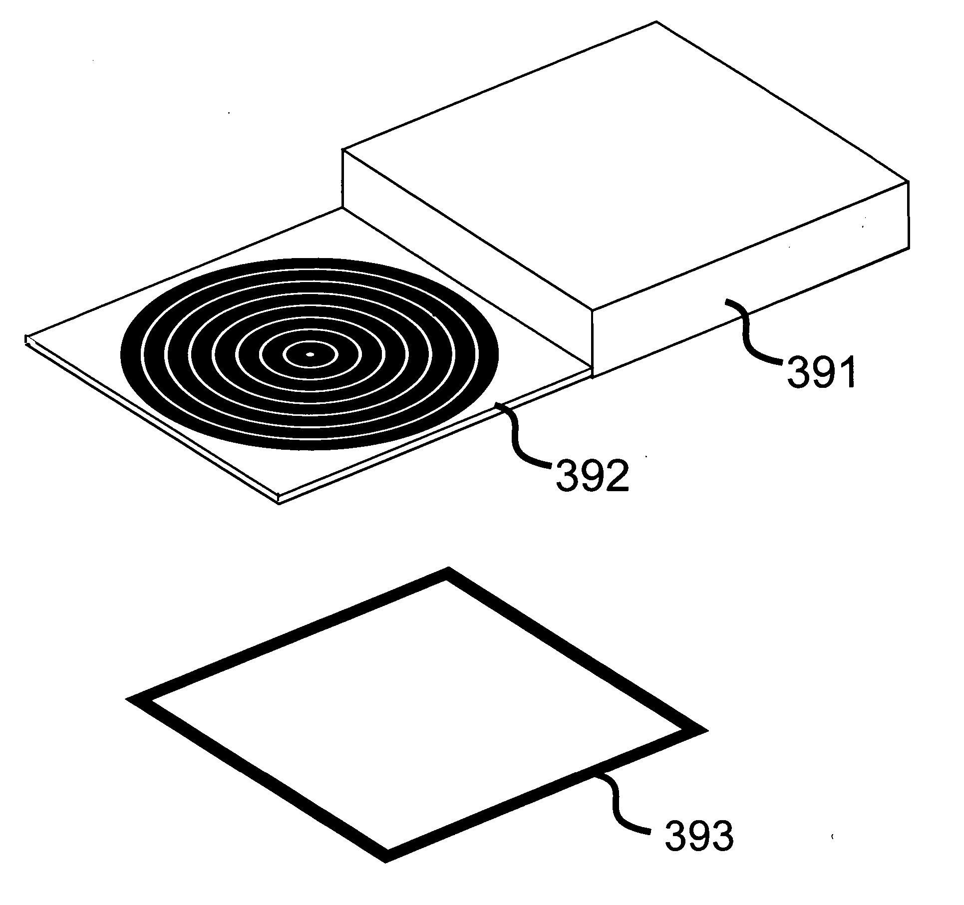
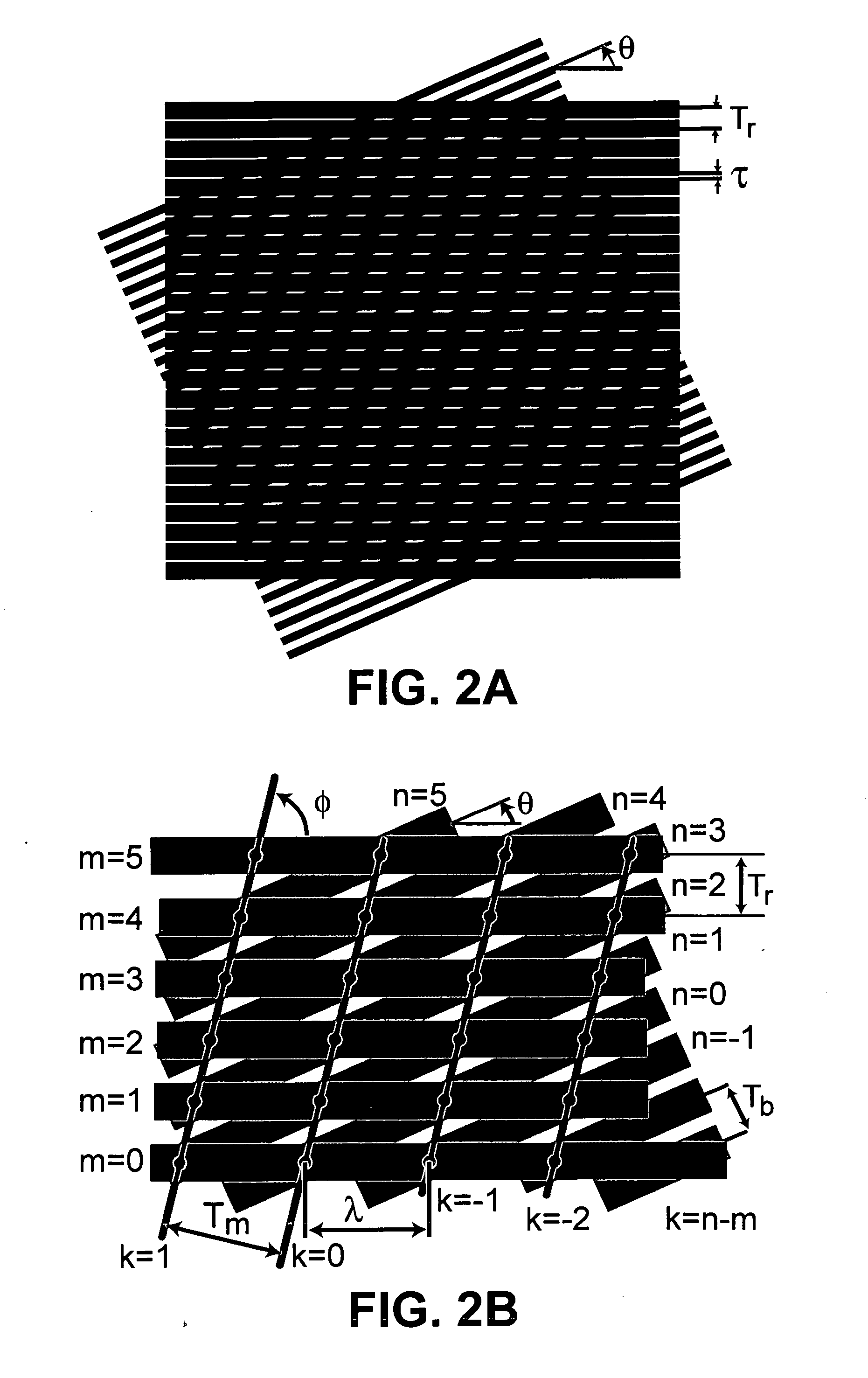
The present invention relies on a band moiré image layout model capable of predicting the band moiré image layer layout produced when superposing a base band grating layer of a given layout and revealing line grating layer of a given layout. Both the base band grating layer and the revealing line grating layer may have a rectilinear or a curvilinear layout. The resulting band moiré image layout may also be rectilinear or curvilinear. Thanks to the band moiré image layout model, one can choose the layout of two layers selected from the set of base band grating layer, revealing line grating layer and band moiré image layer and obtain the layout of the third layer by computation, i.e. automatically. In the case of a concentric band moiré image, base band grating layer and revealing line grating layer layouts may be produced according to geometric transformations, which yield, upon relative displacement of the position sampled by the revealing layer on the base layer, a band moiré image whose patterns move either radially, circularly or according to a spiral trajectory, depending on the orientation of the base band replication vector in the original non-transformed base layer space. In addition, it is possible to conceive a revealing line grating layer which when translated on top of the base band grating layer, generates a band moiré image which is subject to a periodic deformation. Furthermore, thanks also to the availability of a large number of geometric transformations and transformation variants (i.e. different values for the transformation constants), one may create documents having their own individualized document protection. The base band layer and the revealing layer may be separated by a small gap and form a fixed composed layer, where, thanks to the well-known parallax effect, by tilting the composed layer in respect to an observer, different positions of the base layer are sampled and a dynamically moving moiré image is generated. A computing system may automatically generate upon request an individualized protected security document having specific base band grating and revealing line grating layouts. The computing system may then upon request generate and issue a security document incorporating the base band grating layer, a base band grating layer or a revealing line grating layer allowing to authenticate a previously issued security document. The presented methods may be used for creating an individualized protection for various categories of documents (banknotes, identity documents, checks, diploma, travel documents, tickets) and valuable products (optical disks, CDs, DVDs, CD-ROMs, packages for medical drugs, products with affixed labels, watches).

Description

[0001] The present invention is a continuation in part of patent application Ser. No. 10 / 879,218, filed 30th of Jun., 2004. The newly disclosed embodiments comprise a fixed setup of base band layer and revealing line grating layer forming a composed layer, where, thanks to the well-known parallax effect, by tilting the composed layer in respect to the eyes or to an observer, an apparent displacement between base band layer and revealing layer is generated, which yields the dynamic moiré effects described in the parent patent application Ser. No. 10 / 879,218. The present invention also discloses new, non-trivial moiré image effects, such as circular or elliptic rotations of moiré patterns.BACKGROUND OF THE INVENTION [0002] The present invention relates generally to the field of anti-counterfeiting and authentication methods and devices and, more particularly, to methods, security devices and apparatuses for authenticating documents and valuable products by band moiré patterns. [0003] ...

Claims


Application Information

Patent Timeline
Patent Type & Authority Applications(United States)
IPC IPC(8): G06Q99/00
CPCB42D25/342G07D7/2066G07D7/207
Inventor HERSCH, ROGER D.CHOSSON, SYLVAIN
Owner ECOLE POLYTECHNIQUE FEDERALE DE LAUSANNE (EPFL)
Learn More