
Sample-efficient lateral flow immunoassay

Inactive Publication Date: 2006-06-15
KIMBERLY-CLARK WORLDWIDE INC
View PDF14 Cites 69 Cited by
  • Summary
  • Abstract
  • Description
  • Claims
  • Application Information

AI Technical Summary

Benefits of technology

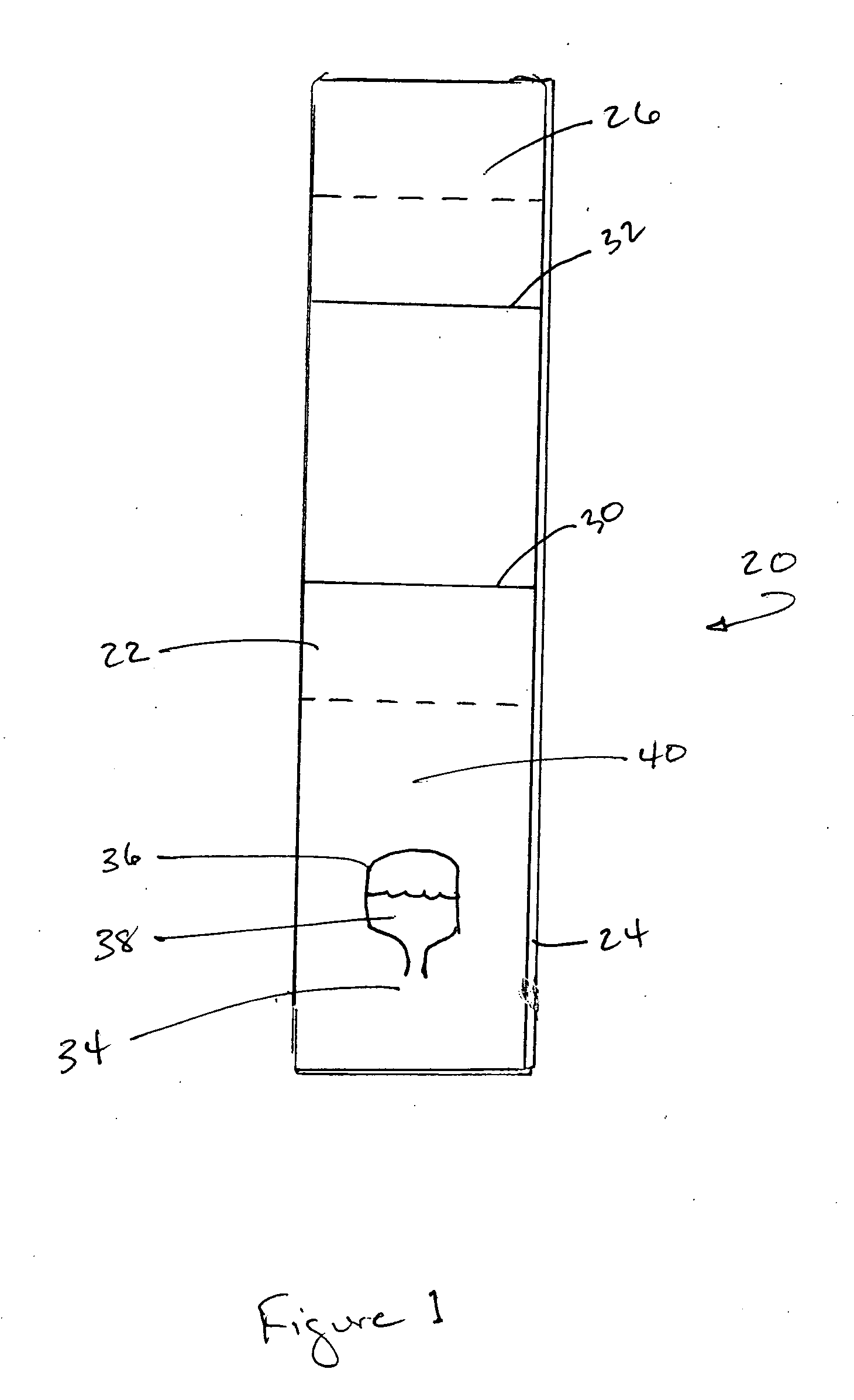
[0007] The control zone is located on the porous membrane downstream from the detection zone. A second capture reagent is immobilized within the control zone that is configured to bind to the conjugate, conjugate-analyte complex or pure probes, to indicate the assay is performing properly. In one embodiment, the second capture reagent is selected from the group consisting of antigens, haptens, polyelectrolytes, protein A or G, neutravidin, avidin, streptavidin, captavidin, primary or secondary antibodies, and complexes thereof.
[0008] The conjugate pad contains detection probes that signal the presence of the analyte. The conjugate pad may also include other, different probe populations, including probes for indication at the control zone. If desired, the detection probes may comprise a substance selected from the group consisting of chromogens, catalysts, luminescent compounds (e.g., fluorescent, phosphorescent, etc.), radioactive compounds, visual labels, particles (e.g., dyed, gold, silver, other optically-

Problems solved by technology

Despite the benefits achieved from these devices, they do not always produce the desired signal (line) intensity.
This limits the circumstances in which they may be used, since the signal may not be visible at low levels of analyte.
Conventional assays may also be rendered less reliable because of the intense red color of a (blood) sample or because of the viscosity of the sample which may cause problems with sample flow.

Method used


Image

  • Sample-efficient lateral flow immunoassay

Examples


example

[0049] This idea was tested with the following experimental setup:

[0050] Goat anti-mouse antibody (“GAM”) was diluted in phosphate-buffered saline (PBS) (pH of 7.2) to 0.1 mg / ml, and striped onto Millipore nitrocellulose HF120 membranes using a Kinematic 1600 coating machine at a dispense rate of 1 ul / cm and a bed speed of 5 cm / s. Scipac C-reactive protein (CRP) (Sittingbourne, Kent, UK) was diluted in water to give a final concentration of 2.6 mg / ml and was striped below the GAM test line at a dispense rate of 1 ul / cm. The cards were left to dry at 37° C. for 1 hour.

[0051] VF2 (from Whatman Corp., Clifton, N.J.) and GF33 (glass fiber) conjugate pad material (from Millipore Corp., Billerica, Mass.) was cut to 30 mm by 34 mm bands using a hand operated guillotine cutter. The monoclonal antibody for the conjugate was Mab1 (catalog number 10-C07, from Fitzgerald Industries International, Inc. of Concord, Mass. 01742-3049 USA). This CRP antibody was conjugated to 20 nm diameter gold p...


PUM

PropertyMeasurementUnit
Luminescenceaaaaaaaaaa

Abstract

There is provided a lateral flow assay device for detecting the presence or quantity of an analyte residing in a test sample where the lateral flow assay device has a porous membrane in communication with a conjugate pad and a wicking pad. The porous membrane has a detection zone which has an immobilized first capture reagent configured to bind to at least a portion of the analyte and analyte-conjugate complexes to generate a detection signal. A control zone may be located downstream from the detection zone on the porous membrane and has a second capture reagent immobilized within the control zone. The conjugate pad is located upstream from the detection zone, and has detection probes with specific binding members for the analyte. The sample is deposited between the control and detection zones. A buffer release zone is located upstream of the conjugate pad and provides for buffer addition to the device, the buffer serving to move the detection probes to the detection and control zones.

Description

BACKGROUND OF THE INVENTION [0001] There are several well-known immunoassay methods that use immunoreactants labeled with a detectable component so that the analyte may be detected analytically. For example, “sandwich-type” assays typically involve mixing the test sample with detectable probes, such as dyed latex or a radioisotope, which are conjugated with a specific binding member for the analyte. The conjugated probes form complexes with the analyte. These complexes then reach a zone of immobilized antibodies where binding occurs between the antibodies and the analyte to form ternary “sandwich complexes.” The sandwich complexes are localized at the zone for detection of the analyte. This technique may be used to obtain quantitative or semi-quantitative results. An alternative technique is the “competitive-type” assay. In a “competitive-type” assay, the label is typically a labeled analyte or analyte-analogue that competes for binding of an antibody with any unlabeled analyte pres...

Claims


Application Information

Patent Timeline
IPC IPC(8): C12Q1/70G01N33/554G01N33/53G01N33/558G01N33/569C12Q1/68
CPCG01N33/558Y02A90/10G01N33/532G01N33/533G01N33/534G01N33/53G01N33/54388
Inventor KAYLOR, ROSANN MARIEWEI, NINGCHIDEBELU-EZE, CHIBUEZEFEASTER, SHAWN RAYCHRISTOPHER, PAUL
Owner KIMBERLY-CLARK WORLDWIDE INC
Learn More