Ultra-thin high-precision glass optic and method of manufacturing same

a technology of ultra-thin, high-precision glass, applied in the direction of printers, instruments, photographic processes, etc., can solve the problems of affecting the quality of light that reaches the substrate, and achieve the effect of improving light transmission

Active Publication Date: 2006-06-15
ASML HLDG NV
View PDF2 Cites 0 Cited by
  • Summary
  • Abstract
  • Description
  • Claims
  • Application Information

AI Technical Summary

Benefits of technology

[0008] An optional anti-reflective coating covers the patterned surface and / or a second parallel surface through which light exits the glass optic. The coating improves light transmission through the glass optic by about four to seven percent for each surface coated.

Problems solved by technology

These conventional techniques disrupt the quality of light that reaches the substrate.

Method used


Image

  • Ultra-thin high-precision glass optic and method of manufacturing same
  • Ultra-thin high-precision glass optic and method of manufacturing same
  • Ultra-thin high-precision glass optic and method of manufacturing same

Examples


Embodiment Construction

[0021] The present invention provides an ultra-thin high-precision glass optic and method of manufacturing the same. It also provides an attenuation system that includes the ultra-thin high-precision glass optic, which is useful for example in photolithography systems / tools. While specific configurations and arrangements are discussed, it should be understood that this is done for illustrative purposes only. Persons skilled in the art(s) will recognize that other configurations and arrangements can be used without departing from the spirit and scope of the present invention. It will be apparent to persons skilled in the pertinent art(s) that this invention can be employed in a variety of other applications.

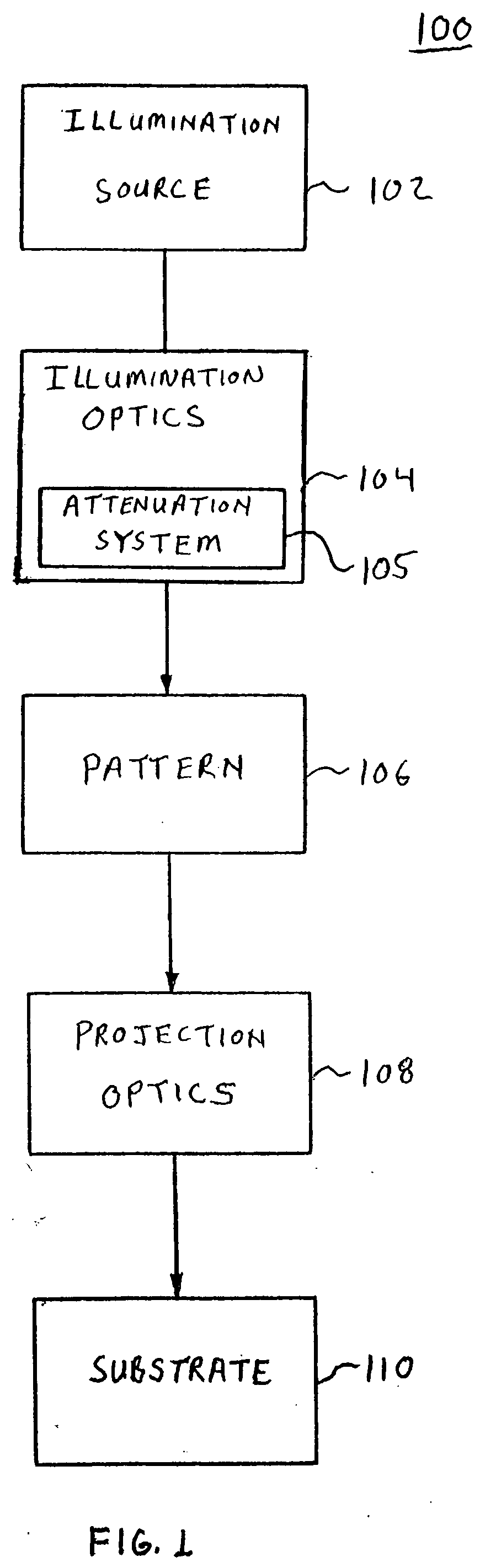
[0022]FIG. 1 is a schematic diagram of an example photolithography system 100 that includes an attenuation system having ultra-thin high-precision glass optics according to an embodiment of the present invention. Photolithography system 100 includes an illumination source 102, il...


PUM

PropertyMeasurementUnit
thicknessaaaaaaaaaa
axial thicknessaaaaaaaaaa

Abstract

The present invention provides an ultra-thin high-precision glass optic and method of manufacturing the same. The optic has an axial thickness that is less than 1,000 microns. A pattern and/or coating is disposed on a surface of the optic to provide attenuation of light in an optical system. In an embodiment, the optic is manufactured by disposing a pattern on a surface of a reticle. The pattern is covered with a first protective coating to protect the pattern. Individual optics are cut from the reticle so that each optic includes a portion of the pattern. The optic is thinned by removing material until it has an axial thickness of less than 1,000 microns. The optic is cleaned after thinning and covered with an anti-reflective coating.

Description

FIELD OF THE INVENTION [0001] The present invention relates to ultra-thin high-precision glass optics for use, for example, in photolithography tools, and methods of manufacturing ultra-thin high-precision glass optics. BACKGROUND OF THE INVENTION [0002] Photolithography systems / tools are used to print features on a substrate in a variety of manufacturing applications. Typically, in operation, a reticle having patterned features is exposed by an illumination source such as, for example, a laser to form images of the features. An optical system projects images of the features onto the substrate. [0003] Conventional photolithography systems control the amount of illumination light that reaches the substrate, for example, by light beam alignment, homogenizers, mechanical trimming, and / or diffractive elements. These conventional techniques disrupt the quality of light that reaches the substrate. [0004] What is needed is a means for attenuating light in a photolithography system, as well...

Claims


Application Information

Patent Timeline
Patent Type & Authority Applications(United States)
IPC IPC(8): G03C5/00G02B6/00G03F1/00G03B27/42
CPCG03F7/70191
Inventor DELUCA, NICHOLAS A.
Owner ASML HLDG NV
Why Eureka
Try Eureka