Retardance measurement system and method

a retardance and measurement system technology, applied in the field of polarized light, can solve the problems of not being well-suited to measuring low retardance specimens, and not providing high sensitivity with low retardance specimens. achieve the effect of high acquisition speed and high accuracy

Inactive Publication Date: 2006-06-15
MARINE BIOLOGICAL LAB
View PDF5 Cites 4 Cited by
  • Summary
  • Abstract
  • Description
  • Claims
  • Application Information

AI Technical Summary

Benefits of technology

[0017] The present invention provides apparatus and methods for measuring retardance and principal plane azimuth distribution in samples. It provides for unsurpassed accuracy and low noise in one embodiment, which requires 4 or 5 intensity readings per measurement. In another embodiment, it provides a measurement of retardance and principal plane azimuth distribution from as few as two or three specimen readings together with background readings that are taken once and need not be repeated with each measurement. Thus the present invention provides full information about retardance and azimuth angle with improved noise than the prior art, or with fewer readings required per measurement, or both. It is well-suited for use with an imaging detector to produce two-dimensional retardance images of a specimen. These and other aspects of the invention will be clear from the description provided below.
[0024] These algorithms allow one to optimize the measurement for speed, sensitivity, and accuracy. The highest accuracy can be achieved using the 5-frame technique, and in the 4-frame algorithm without extinction setting. Alternatively, when high acquisition speed is important, as when imaging a moving sample, the two-frame algorithm or three-frame algorithm is valuable.

Problems solved by technology

The technique doesn't provide high sensitivity with low retardance specimens, and describes use of a polarization state analyzer comprising a rotated quarter waveplate and rotated linear analyzer.
The device is not suitable for measuring low retardance specimens because it is strongly susceptible to light intensity variations, photon statistical noise, detector read-out noise, and digitization error.
While there have thus been shown various techniques for retardance measurement and two-dimensional retardance imaging, the existing techniques in the art require taking six or more readings; or are not well-suited to measurement of low-retardance samples; or do not operate with high speed; or offer less than adequate accuracy or noise.

Method used


Image

  • Retardance measurement system and method
  • Retardance measurement system and method
  • Retardance measurement system and method

Examples


second embodiment

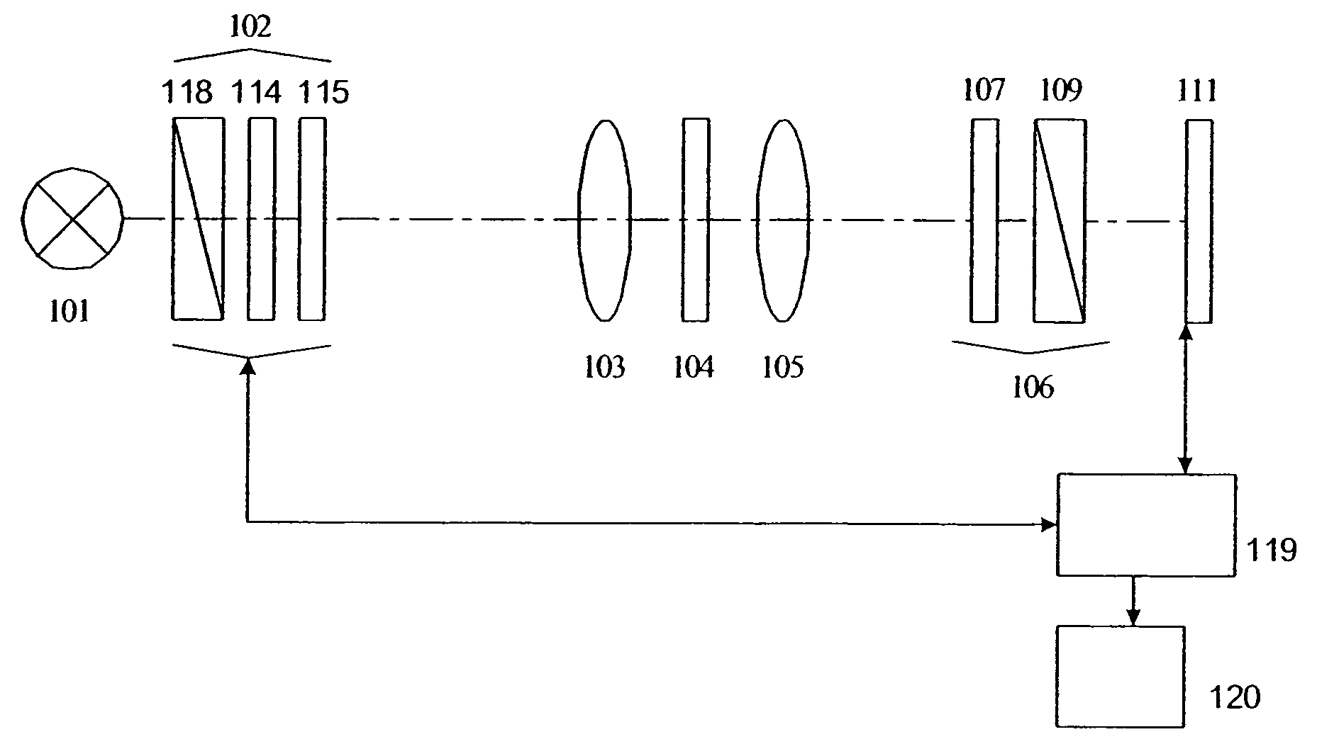
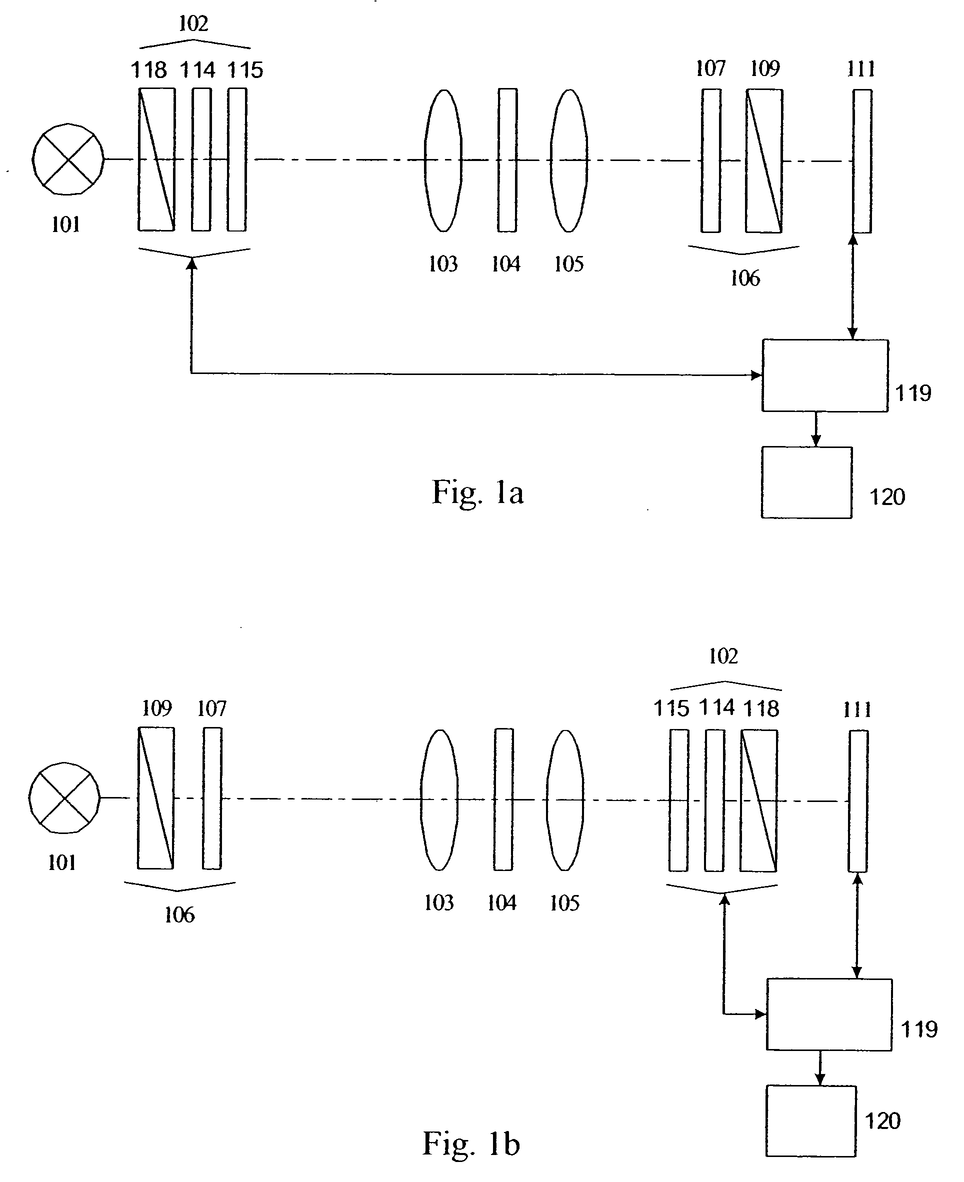
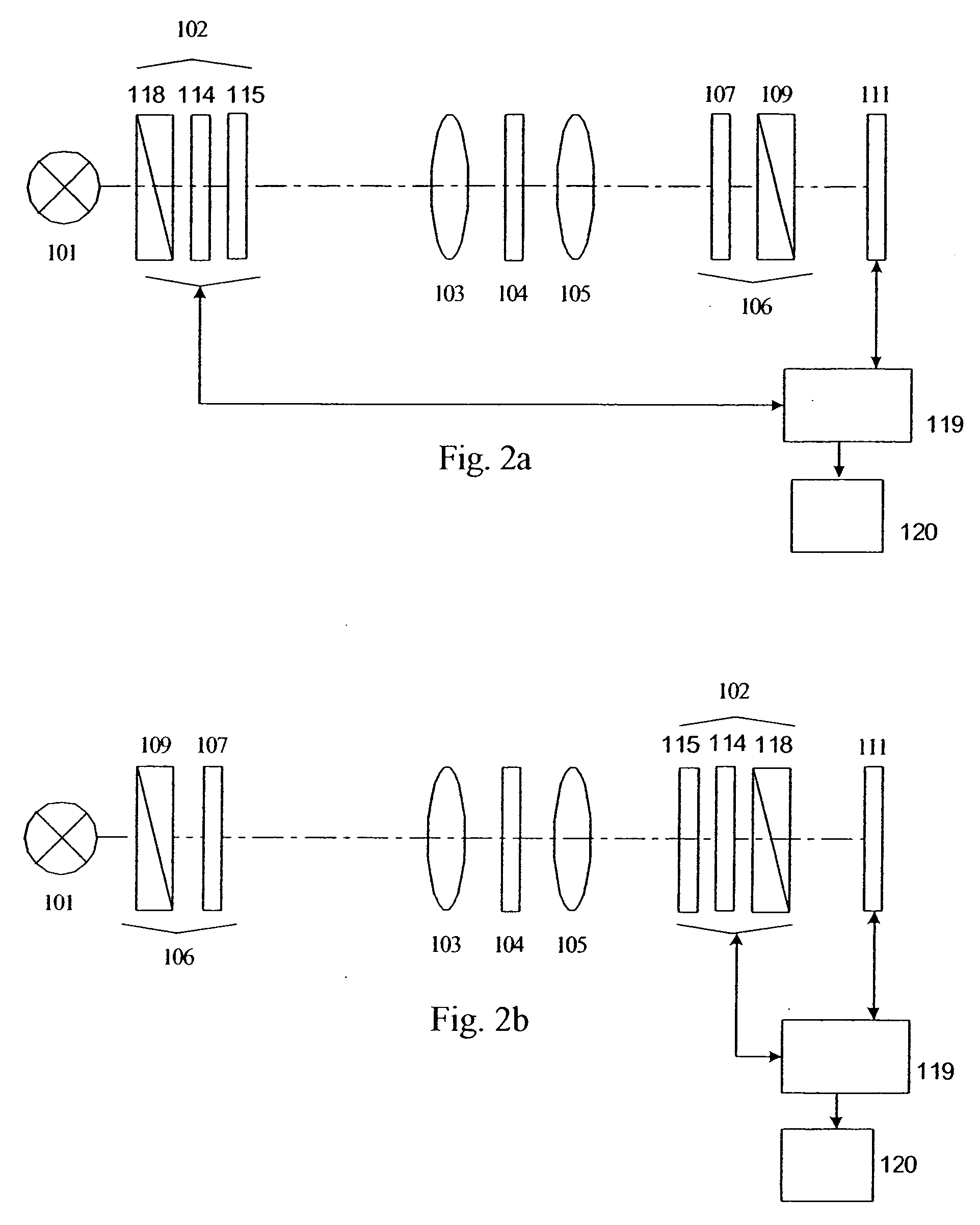
[0060] In a second embodiment, N=3 and the states used are χ1, χ2, and χ3. From the images, one derives the quantities:

A≡[(I1−I3) / (I1+I2)]*tan(c / 2)  [5a]

B≡[(I2−I3) / (I1+I2)]*tan(c / 2)  [5b]

from which the retardance δ and azimuth angle φ are calculated as:

δ=2 arctan{[21 / 2Z] / [1+(1−2[Z / tan(c / 2)]2)1 / 2]}  [6a]

φ=½ arctan (A / B)−22.5°  [6b]

where

Z=(A2+B2)1 / 2  [6c]

[0061] This embodiment provides better signal-to-noise than the N=2 embodiment, and works well in situations where the optical equipment has a high extinction ratio, such as 200:1 or better.

Embodiment with N=5

third embodiment

[0062] In a third embodiment, N=5. All states are used, χ0-χ4, to obtain images I0-I4. From these, one determines the quantities A and B as

A≡[(I1−I2) / (I1+I2−2I0)]*tan(c / 2)  [7a]

B=[(I4−I3) / (I4+I3−2I0)]*tan(c / 2)  [7b]

from which the retardance δ and azimuth φ are calculated as

δ=arctan(Z) when I1+I2−2I0≧0  [8a]

δ=180°−arctan(Z) when I1+I2−2I0<0  [8b]

φ=½ arctan (A / B)  [8c]

[0063] This embodiment has the highest sensitivity of all the embodiments, and has equal sensitivity for all retardance azimuth values.

Embodiment with N=4

fourth embodiment

[0064] In a fourth embodiment, N=4. The extinction state χ0 is not used. Instead, the four states used are χ1, χ2, χ3, and χ4, resulting in images I1-I4. From these, the parameters A and B are calculated as:

A=[(I1−I2) / (I1+I2)] tan(c / 2)  [9a]

B=[(I4−I3) / (I4+I3)] tan(c / 2)  [9b]

from which the retardance δ and azimuth angle φ are calculated as:

δ=2 arctan(Z / [1+(1−[Z / tan(c / 2)]2)1 / 2])  [10a]

φ=½ arctan (A / B)  [10b]

[0065] This system offers good sensitivity and, like the previous embodiment, the retardance sensitivity is independent of azimuth angle. However, it requires that the optical apparatus have a high extinction, such as 200:1, for best performance.

[0066] For any of the above embodiments that omit one or more of the states χ1-χ4, there are equivalent alternatives that can be used equally well. For example, instead of using χ1 and χ3, one might use χ3 and χ2, or χ2 and χ4, and so on. These variations consist of the embodiments described above, except that the elliptical polarizers e...


PUM

PropertyMeasurementUnit
azimuth angleaaaaaaaaaa
angleaaaaaaaaaa

Abstract

Apparatus and methods for measuring retardance and slow axis azimuth in sample specimens. The invention can be used in imaging systems that obtain retardance and slow axis azimuth orientation at all points in a two-dimensional image simultaneously. A sample is illuminated by circularly polarized monochromatic light which is then analyzed by an elliptical analyzer at different settings. In another embodiment, light conditioned by an elliptical polarizer at various settings illuminates a specimen and the beam exiting the sample is analyzed by a circular analyzer. The elliptical analyzer / polarizer may have selectable ellipticity and azimuth angle, including in some cases a setting of circular polarization. Background images obtained with selected settings of the elliptical analyzer / polarizer, but without the sample present, are used in some embodiments to improve the measurement. Algorithms are described which employ two specimen images with elliptical settings and three or two background images; or which employ three specimen images with elliptical settings; or which employ four specimen images with elliptical settings without an extinction setting; or which employ five specimen images with four elliptical settings and one extinction setting. These algorithms allow one to variously optimize measurements for speed, sensitivity, and accuracy.

Description

[0001] This application is a Divisional of U.S. patent application Ser. No. 10 / 616,080, filed Jul. 8, 2003.BACKGROUND OF THE INVENTION [0002] 1. Field of the Invention [0003] The present invention is related to polarized light and, more particularly, to measurement of retardance and slow axis azimuth angle, and most especially to systems that produce images of these properties in a two-dimensional image of a sample. [0004] 2. Description of the Related Art [0005] Measuring of two-dimensional birefringence distributions is an established technique for analyzing the structure of various specimens. It can also be applied to study the vector or tensor fields associated with birefringence. [0006] The application of two-dimensional birefringence measurements to the analysis of inner stress in construction models using photoelasticity is also well known (Handbook on Experimental Mechanics, Ed. by Albert S. Kobayashi, Prentice Hall: Englewood Cliffs, 1987). E. A. Patterson and co-authors of...

Claims


Application Information

Patent Timeline
Patent Type & Authority Applications(United States)
IPC IPC(8): G01J4/00G01N21/19G01N21/27
CPCG01J4/00G01N21/19G01N21/276
Inventor SHRIBAK, MYKHAILOOLDENBOURG, RUDOLF
Owner MARINE BIOLOGICAL LAB
Why Eureka
Try Eureka