
Acyclic modeling of combinational loops

a combinational loop and acyclic modeling technology, applied in the direction of cad circuit design, program control, instruments, etc., can solve the problem of linear loop size and time complexity of the loop transformation methodology, and achieve the effect of increasing the design area

Active Publication Date: 2006-06-08
SIEMENS PROD LIFECYCLE MANAGEMENT SOFTWARE INC
View PDF2 Cites 6 Cited by
  • Summary
  • Abstract
  • Description
  • Claims
  • Application Information

AI Technical Summary

Benefits of technology

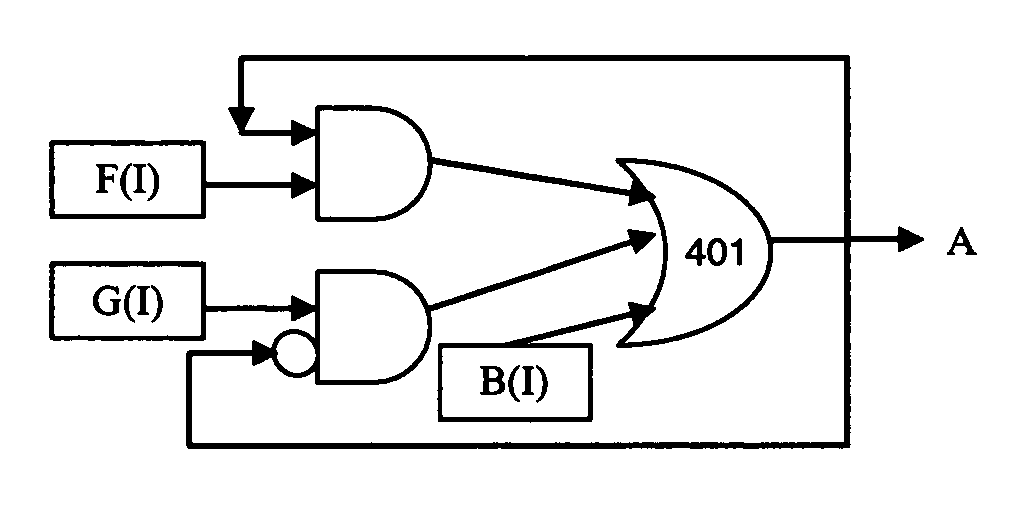
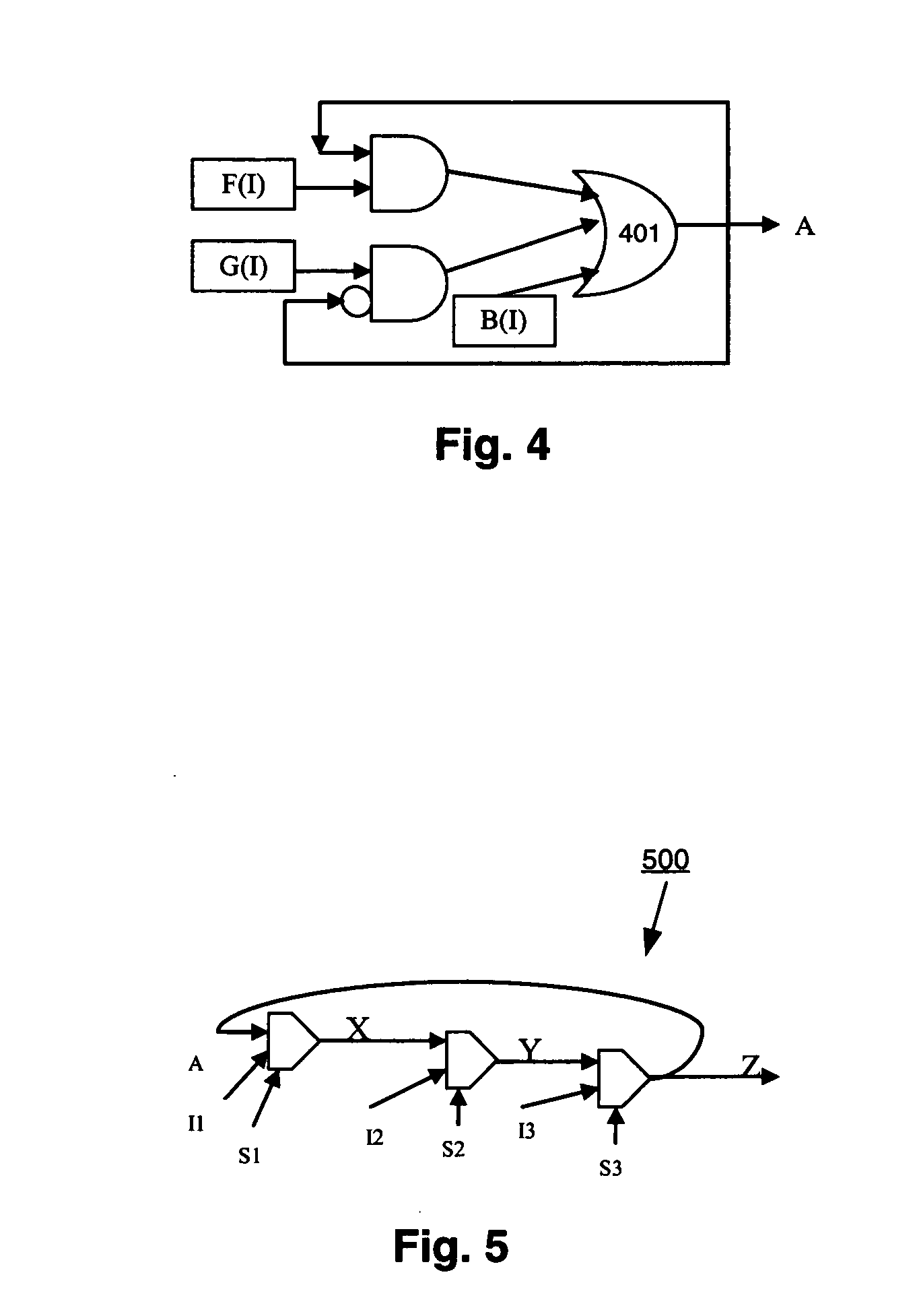
[0008] Aspects of the present invention are directed to converting non-oscillatory combinational loops into acyclic circuits. Combinational loops may be modeled as state-holding elements where non-oscillatory loops are effectively broken using edge-sensitive latches. In addition to providing a way to model combinational loops originally consisting only of gates (i.e., without originally including any state-holding elements), loops that have paths through user latches may also be successfully converted. Any increase in design area that may be realized by loop conversion has an upper bound of twice the size of the original loop. In addition, the loop transformation methodology has a time complexity that is linear with respect to loop size. Thus, the presented methodology works well with both small and large loops.
[0009] Accordingly, circuit designers may feel as though they have more freedom in their designs, because designers need not be as concerned about whether loops may be synthesized. This means that designers may be more likely to design circuits at a high level the way that the designers actually intend them. This also means that the design process may be faster and more efficient as there is now one less restriction on the designer.

Problems solved by technology

In addition, the loop transformation methodology has a time complexity that is linear with respect to loop size.

Method used


Image

  • Acyclic modeling of combinational loops
  • Acyclic modeling of combinational loops
  • Acyclic modeling of combinational loops

Examples


Embodiment Construction

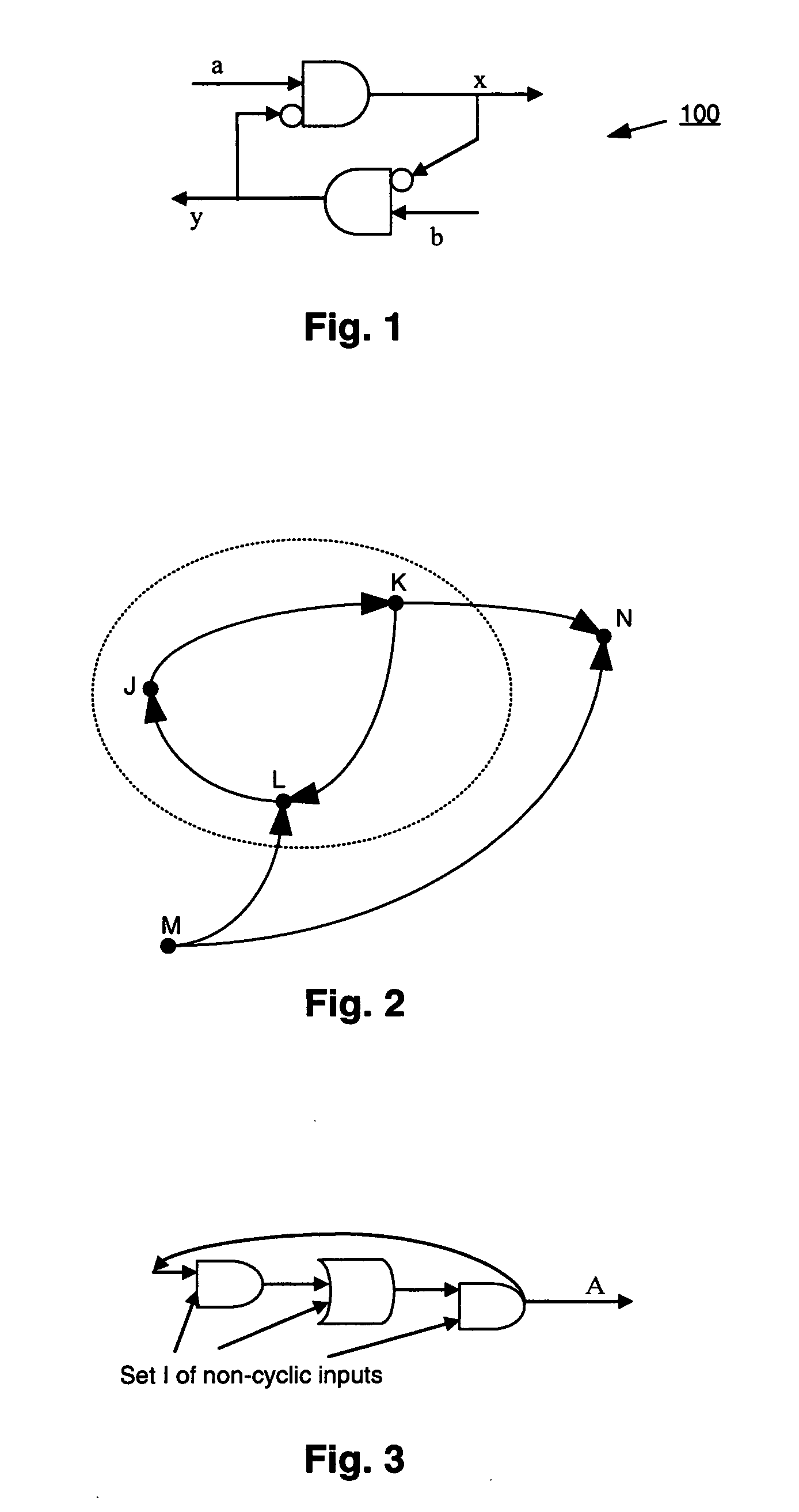
[0021] Aspects of the present invention may be viewed as improvements to previous methodologies, although a completely different analysis is used. An improvement lies in the fact that previous methodologies assert that the combinational loop 100 shown in FIG. 1, for example, is convertible to a non-loop equivalent unless a=b=1. However, in accordance with aspects of the present invention, combinational loop 100 is determined to be a “safe” loop that can be converted to a non-loop equivalent. This is because where a=b=1 in this example, then both x and y hold their previous values and a state-holding element such as a latch may be used to model x and y as an acyclic circuit.

1.0 Modeling Combinational Loops

[0022] Aspects of the present invention provide a compelling computer-implemented solution to modeling combinational loops as acyclic circuit in gate level designs. An efficient and linear-time solution is provided that detects the fixed-point behavior of combinational loops in g...


PUM


Abstract

Aspects of the present invention are directed to converting non-oscillatory combinational loops into acyclic circuits. Combinational loops may be modeled as state-holding elements where non-oscillatory loops are broken using edge-sensitive latches. In addition to providing a way to model combinational loops originally consisting only of gates (i.e., without originally including any state-holding elements), loops that have paths through user latches may also be converted. The presented methodology may be used with both small and large loops.

Description

RELATED APPLICATIONS [0001] This application claims priority to U.S. provisional patent application Ser. No. 60 / 627,172, filed Nov. 15, 2004, incorporated herein by reference as to its entirety.FIELD OF THE INVENTION [0002] Aspects of the present invention are directed to the acyclic modeling of combinational loops in circuit designs. BACKGROUND [0003] Traditionally, circuits with combinational loops are found only in asynchronous designs. Combinational loops also arise in synchronous circuits as a result of automated synthesis tools converting an RTL-level description to a gate level description. In some cases, combinational loops are synthesized intentionally by a synthesis compiler for area optimization. However, combinational loops in designs are always undesirable. A combinational loop or feedback path implies a mutual dependence of a signal on itself with zero delay. Zero delay semantics necessitate special handling in designing cycle-accurate simulators or statically schedule...

Claims


Application Information

Patent Timeline
IPC IPC(8): G01R31/28G06F11/00
CPCG06F17/505G06F17/5059G06F30/327G06F30/35
Inventor GUPTA, AMITSELVIDGE, CHARLES W.
Owner SIEMENS PROD LIFECYCLE MANAGEMENT SOFTWARE INC
Learn More