
Particles based electrodes and methods of making same

Active Publication Date: 2006-06-01
TESLA INC
View PDF49 Cites 52 Cited by
  • Summary
  • Abstract
  • Description
  • Claims
  • Application Information

AI Technical Summary

Benefits of technology

[0012] In accordance with embodiments of the present invention, fibrillizable polymers and methods of using in manufacture of energy storage devices are described. The present invention provides methods for making long lasting, durable, and inexpensive energy storage devices, for example, capacitors. Fibrillization of the polymers may provided without the use of any processing additives. Further fibrillization may be provided to in other later steps. The present invention provides distinct advantages when compared to that of the coating based methods of the prior art. A high throughput method for making more durable and more reliable coating based energy storage devices is provided.

Problems solved by technology

Although, double-layer capacitors can theoretically be operated at voltages as high as 4.0 volts and possibly higher, current double-layer capacitor manufacturing technologies limit nominal operating voltages of double-layer capacitors to about 2.5 to 2.7 volts.
Higher operating voltages are possible, but at such voltages undesirable destructive breakdown begins to occur, which in part may be due to interactions with impurities and residues that can be introduced during manufacture.
For example, undesirable destructive breakdown of double-layer capacitors is seen to appear at voltages between about 2.7 to 3.0 volts.
Among the numerous polymers and copolymers that can be used as a binder in the coating process, most of them suffer from a lack of stability when a subsequent electrolyte solvent is used to impregnate a final capacitor product.
This is especially true when the solvent is an organic one and the working or storage temperature is higher than 65° C. Instability of the binder can lead to a premature failure of an electrode and, thus a capacitor.
During prior art extrusion and / or coating and / or subsequent calendering stages, although fibrillization is known to occur, such processes also cause a large number of the fibrillized binder particles to re / coalesce and be formed into agglomerates.
The large number of such re / coalesced binder particles results in a reduced final film integrity and performance.
Because fluoropolymers do not dissolve in most solvents, they are not suited for use as a binder in conventional solvent based coating processes.
Because extrusion processes require large manufacturing equipment investments, it is often financially prohibitive for electrode manufacturers to adopt manufacturing processes that take advantage of the benefits of using fluoropolymers as a binder.

Method used

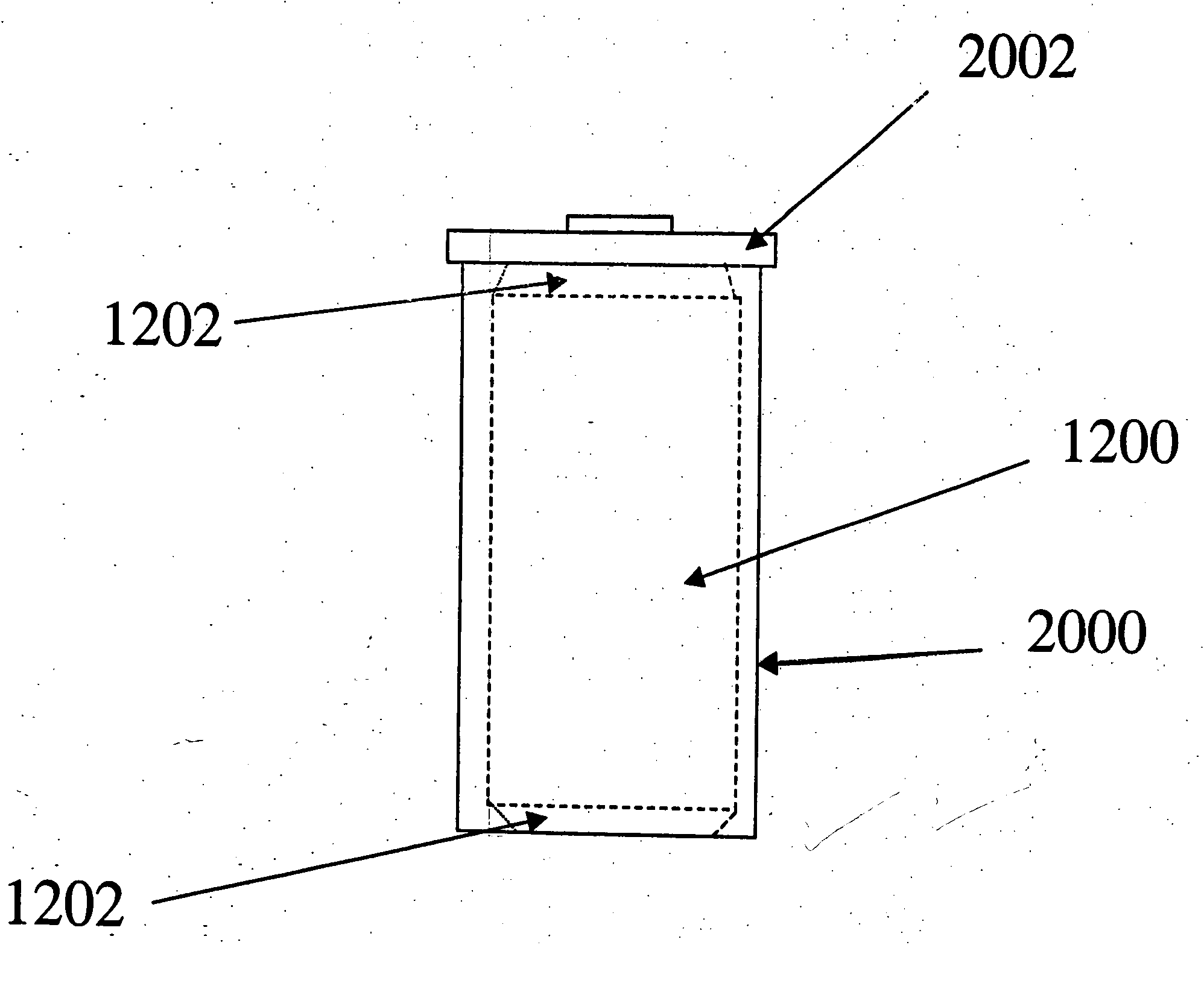
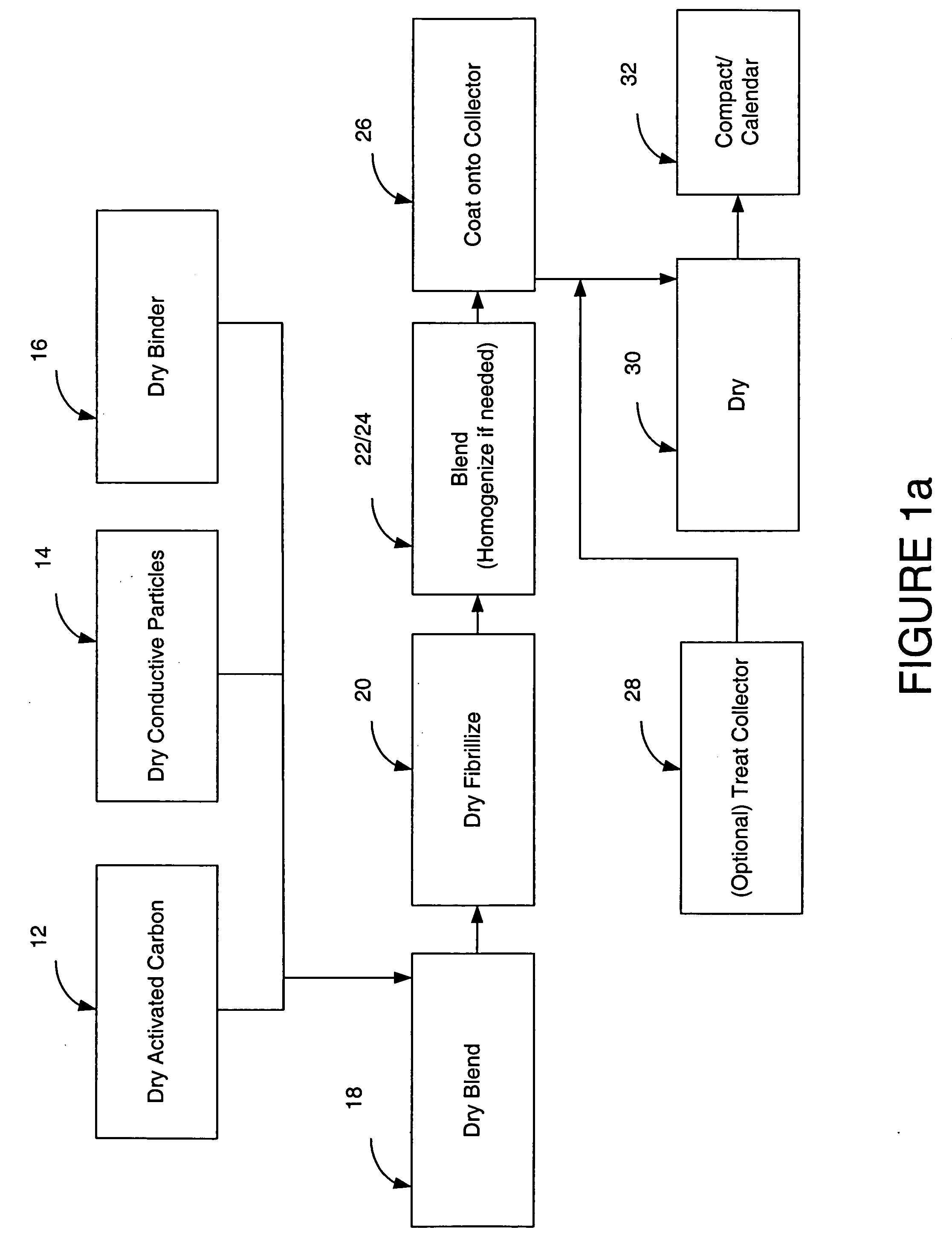
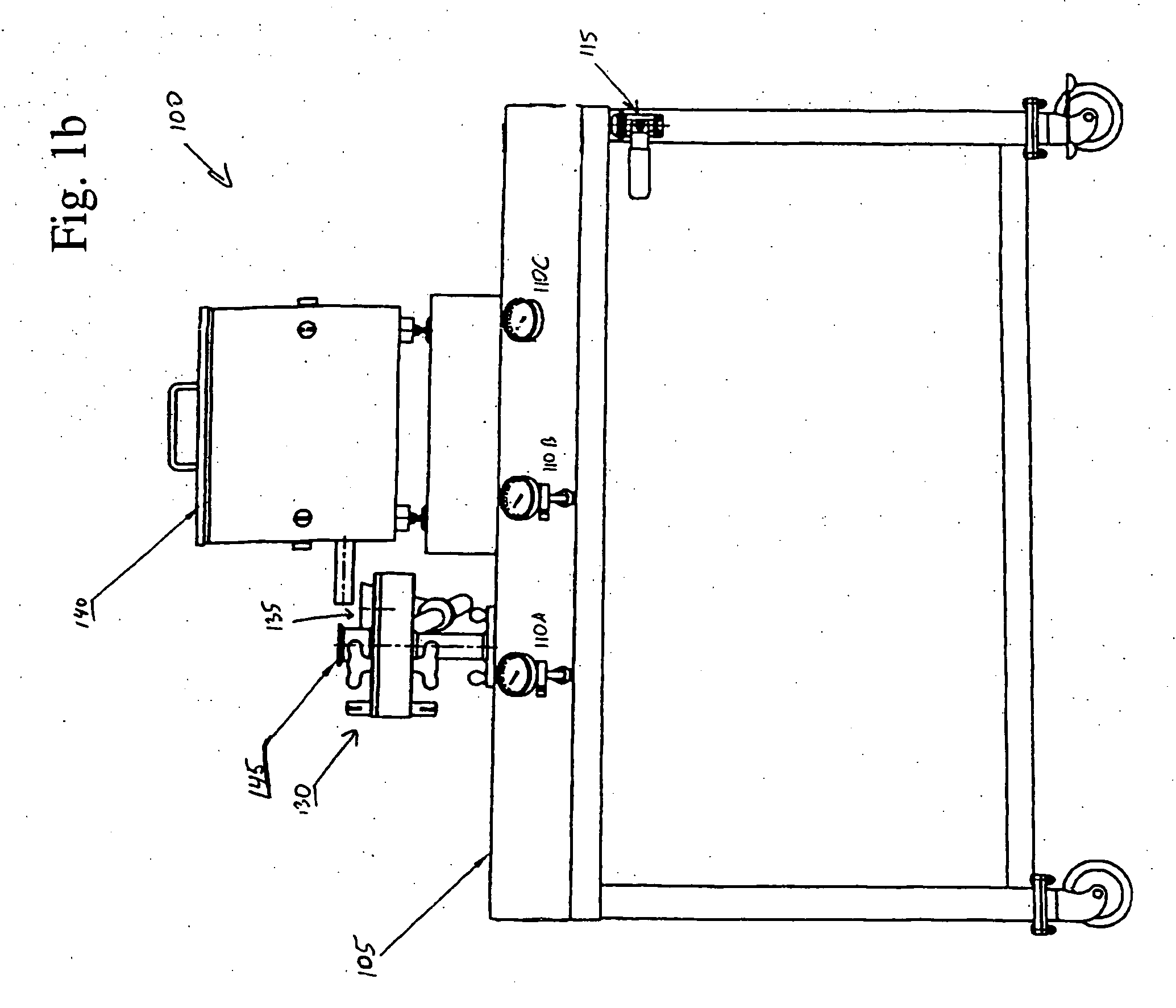

Image

  • Particles based electrodes and methods of making same
  • Particles based electrodes and methods of making same
  • Particles based electrodes and methods of making same

Examples


Embodiment Construction

[0037] Reference will now be made in detail to several embodiments of the invention that are illustrated in the accompanying drawings. In accordance with embodiments of the present invention, fibrillizable polymers and methods of using in manufacture of energy storage devices are described. The present invention provides methods for making long lasting, durable, and inexpensive energy storage devices, for example, capacitors. Fibrillization of the polymers may effectuated without the use of any processing additives. The present invention provides distinct advantages when compared to that of the coating based methods of the prior art. A high throughput method for making more durable and more reliable coating based energy storage devices is provided.

[0038] In the embodiments that follow, it will be understood that reference to no-use and non-use of additive(s) in the manufacture of an energy storage device according to the present invention takes into account that electrolyte may be ...


PUM


Abstract

A coated electrode is provided for use in energy storage devices. The coated electrode comprises a dry particles that are fibrillized.

Description

RELATED APPLICATIONS [0001] The present application is a Continuation-In-Part of of U.S. patent application Ser. No. 10 / 817,589, filed Apr. 2, 2004, Attorney Docket Number 026471-0901 US.FIELD OF THE INVENTION [0002] The present invention relates generally to the field of coating of structures for use in energy storage devices. More particularly, the present invention relates to capacitor structures and methods that use dry fibrillized fluoropolymers. BACKGROUND INFORMATION [0003] Double-layer capacitors, also referred to as ultracapacitors and super-capacitors, are energy storage devices that are able to store more energy per unit weight and unit volume than capacitors made with traditional technology. [0004] Double-layer capacitors store electrostatic energy in a polarized electrode / electrolyte interface layer. Double-layer capacitors include two electrodes, which are separated from contact by a porous separator. The separator prevents an electronic (as opposed to an ionic) curren...

Claims


Application Information

Patent Timeline
IPC IPC(8): H01G9/00
CPCH01G11/42H01G11/86H01M4/02H01M4/0404H01M4/0409H01M4/0435H01M4/587H01M4/8817H01M4/8828H01M4/8832H01M4/96Y02E60/50H01G11/28Y02E60/13Y02E60/10
Inventor MITCHELL, PORTERZHONG, LINDAHERMANN, VINCENTNANJUDIAH, CHENNIA
Owner TESLA INC
Learn More