
Low cost vehicle fuel system components manufactured from conductive loaded resin-based materials

a technology of conductive loading and fuel system components, which is applied in the direction of synthetic resin layered products, machines/engines, packaging, etc., can solve the problems of high manufacturing cost, metal-based components can be very heavy, and the material should not support the build-up of electrostatic charges, etc., to achieve excellent conductivity and electrostatic charge dissipation ability, and reduce weight

Inactive Publication Date: 2006-06-01
INTEGRAL TECHNOLOGY INC
View PDF3 Cites 27 Cited by
  • Summary
  • Abstract
  • Description
  • Claims
  • Application Information

AI Technical Summary

Benefits of technology

[0013] A further object of the present invention is to provide a vehicle fuel system component having reduced weight.
[0014] A further object of the present invention is to provide a vehicle fuel system component having excellent conductivity and electrostatic charge dissipation capability.

Problems solved by technology

In addition, the material should not support the build-up of electrostatic charge.
However, metal-based components can be very heavy and can be expensive to manufacture.

Method used


Image

  • Low cost vehicle fuel system components manufactured from conductive loaded resin-based materials
  • Low cost vehicle fuel system components manufactured from conductive loaded resin-based materials
  • Low cost vehicle fuel system components manufactured from conductive loaded resin-based materials

Examples


third embodiment

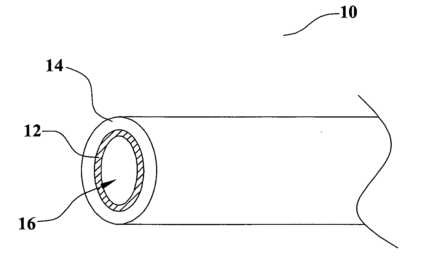
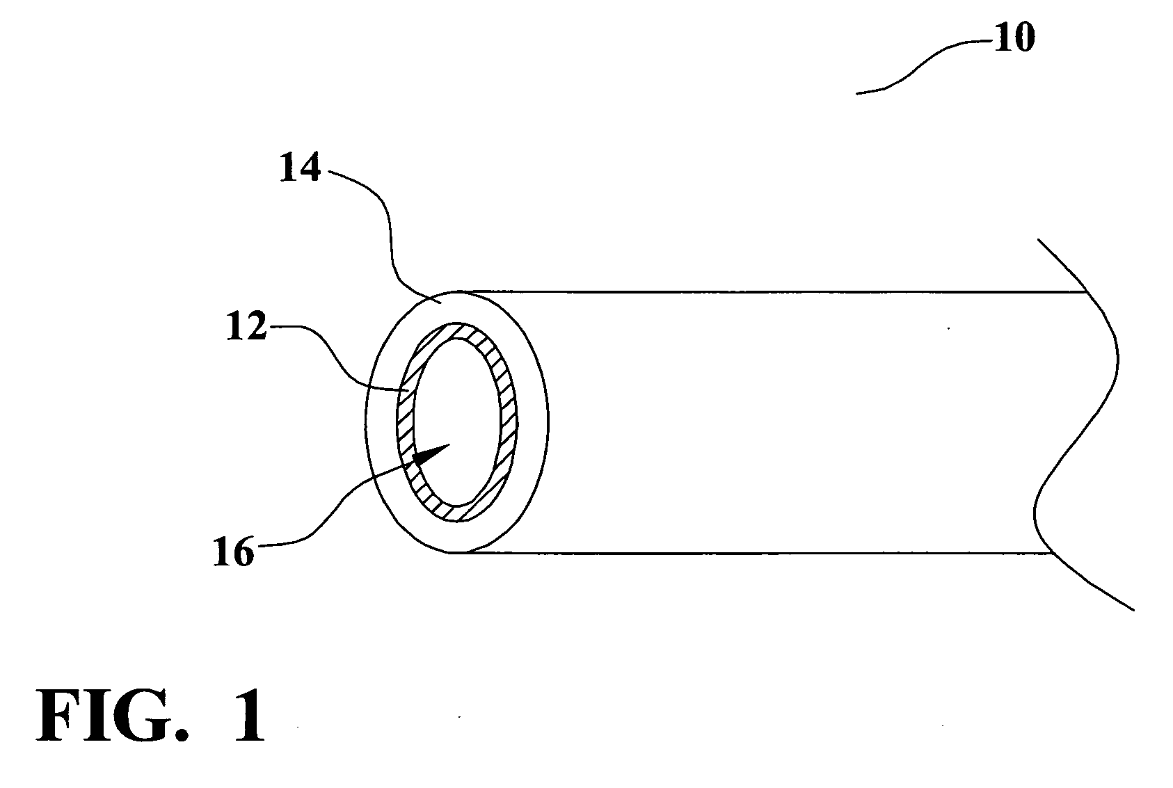
[0063] Referring now to FIG. 1, a first preferred embodiment of the present invention is illustrated. One of the preferred embodiments of the conductive loaded resin-based material in realizing a low cost fuel hose 10. Fuel hoses are used in vehicles to transport fuel from one location to another location. The exemplary fuel hose 10 is required to have many specific properties including gasoline resistance, gasohol resistance, fuel impermeability, and moisture impermeability. Further, the inner peripheral wall of the fuel hose is required to be electrically conductive in order to discharge static electricity. More specifically, the inner layer 12 is presently required to provide a conductivity of surface resistance (ASTM D 991) of 1010 ohms or less. The fuel hose 10 comprises an inner layer 12 and an outer layer 14. The inner layer 12 comprises conductive loaded resin-based material according to the present invention. This conductive loaded resin-based material provides the conducti...

first embodiment

[0067] In the conductive loaded resin-based material fuel tank 130, as described above, the entire fuel tank comprises conductive loaded resin-based material. This material provides the electrical conductivity needed for static electricity discharge. With the proper base resin and conductive loader selection, the conductive loaded resin-based material fuel tank 130 also provides the necessary chemical resistance, impermeability, and strength needed for this application. Still referring to FIG. 8, as an alternate embodiment the conductive loaded resin-based material is coated or plated with metal. The metal outer layer, not shown, is used to provide such features as additional impermeability, durability to stone impingement, visual characteristics, or other desirable properties. Yet another embodiment of FIG. 8 comprises multiple layers of resin-based materials, not shown, with at least one of these layers comprising conductive loaded resin-based material of the present invention. Ea...


PUM

PropertyMeasurementUnit
Fractionaaaaaaaaaa
Fractionaaaaaaaaaa
Fractionaaaaaaaaaa

Abstract

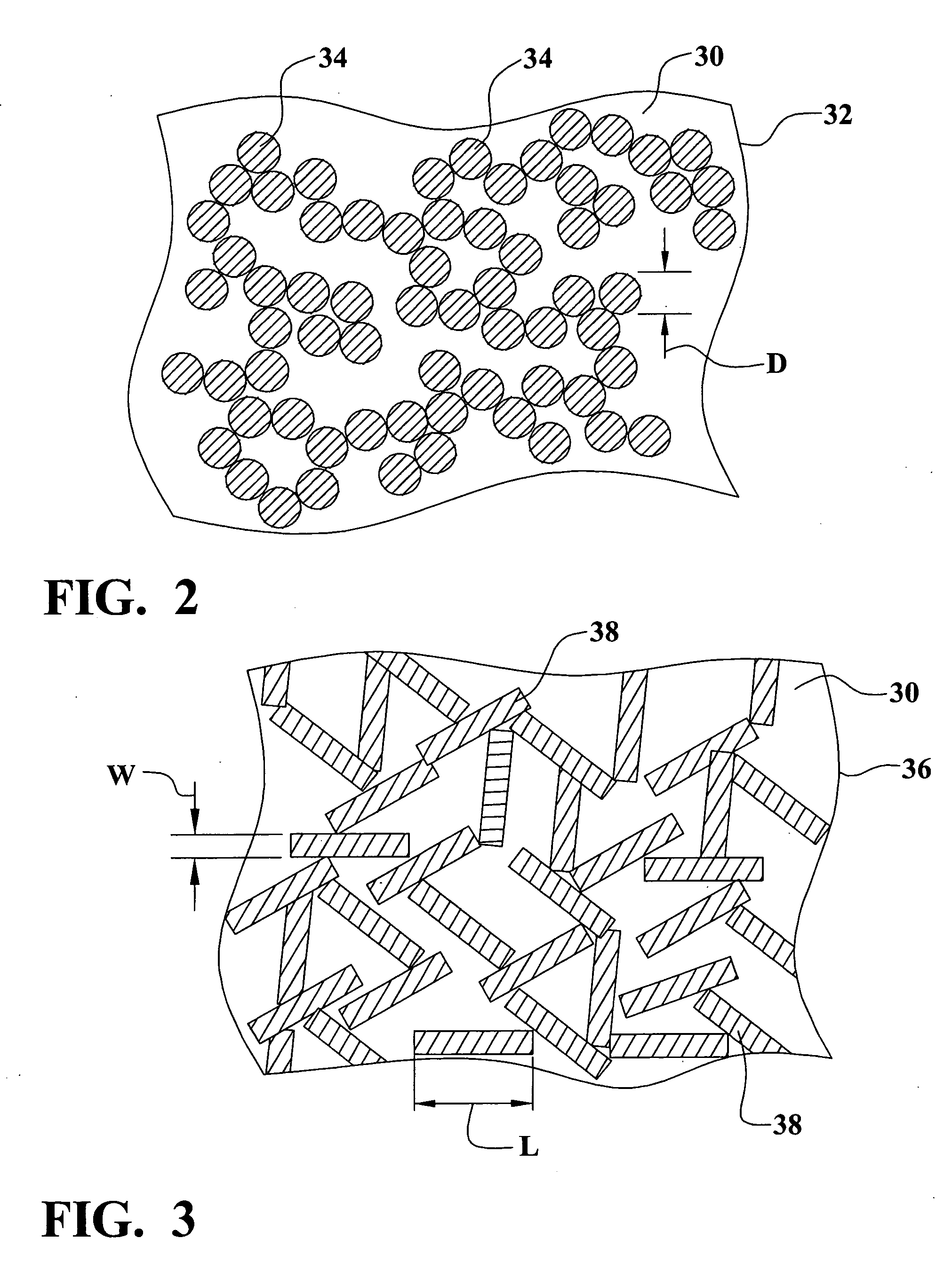
Vehicle fuel system components are formed of a conductive loaded resin-based material. The conductive loaded resin-based material comprises micron conductive powder(s), conductive fiber(s), or a combination of conductive powder and conductive fibers in a base resin host. The percentage by weight of the conductive powder(s), conductive fiber(s), or a combination thereof is between about 20% and 50% of the weight of the conductive loaded resin-based material. The micron conductive powders are metals or conductive non-metals or metal plated non-metals. The micron conductive fibers may be metal fiber or metal plated fiber. Further, the metal plated fiber may be formed by plating metal onto a metal fiber or by plating metal onto a non-metal fiber. Any platable fiber may be used as the core for a non-metal fiber. Superconductor metals may also be used as micron conductive fibers and / or as metal plating onto fibers in the present invention.

Description

RELATED PATENT APPLICATIONS [0001] This Patent Application is related to U.S. patent application INT04-025A, Ser. No. ______, and filed on ______ which is herein incorporated by reference in its entirety. [0002] This Patent Application claims priority to the U.S. Provisional Patent Application 60 / 587,289 filed on Jul. 12, 2004, which is herein incorporated by reference in its entirety. [0003] This Patent Application is a Continuation-in-Part of INT01-002CIPC, filed as U.S. patent application Ser. No. 10 / 877,092, filed on Jun. 25, 2004, which is a Continuation of INT01-002CIP, filed as U.S. patent application Ser. No. 10 / 309,429, filed on Dec. 4, 2002, now issued as U.S. Pat. No. 6,870,516, also incorporated by reference in its entirety, which is a Continuation-in-Part application of docket number INT01-002, filed as U.S. patent application Ser. No. 10 / 075,778, filed on Feb. 14, 2002, now issued as U.S. Pat. No. 6,741,221, which claimed priority to US Provisional Patent Applications ...

Claims


Application Information

Patent Timeline
IPC IPC(8): C04B35/00B29D23/00
CPCB29C45/0005B29C45/0013B29C47/00B29C47/0004B29C47/0023B29C47/0033B29C47/0038B29C70/025B29C70/12B29C70/60B29C70/882B29K2105/0023B29K2305/00B29K2305/10B29K2305/12B29K2305/14B29K2307/00B29K2995/0005B29K2995/0008B29L2023/005B29L2023/22B29L2031/565B29L2031/7172B32B1/02B32B1/08B32B7/02B32B27/08B32B27/18B32B2250/02B32B2250/24B32B2255/10B32B2255/205B32B2262/0276B32B2262/103B32B2262/106B32B2264/105B32B2307/202B32B2307/206B32B2307/714B32B2307/7242B32B2307/7265B32B2439/40B32B2597/00B32B2605/08B60K15/00B60K2015/03039B60K2015/03401F02D33/003F02M37/0017F02M37/10F16L11/127F16L11/20F16L2011/047B29C47/0028B29C47/065B29C48/00B29C48/022B29C48/09B29C48/11B29C48/13B29C48/001B29C48/21B32B1/00
Inventor AISENBREY, THOMAS
Owner INTEGRAL TECHNOLOGY INC
Learn More