
Metallic prosthetic implant for use in minimally invasive acromio-clavicular shoulder joint hemi-arthroplasty

a hemi-arthroplasty and clavicle technology, applied in the field of metal prosthetic implants, can solve the problems of high probability of persistent pain and disability, complex prior art, and prolonged recovery time, and achieve the effects of less recovery time, less trauma, and minimal invasiveness

Inactive Publication Date: 2006-05-25
MINSURG INT
View PDF99 Cites 5 Cited by
  • Summary
  • Abstract
  • Description
  • Claims
  • Application Information

AI Technical Summary

Benefits of technology

[0005] The use of a pre-shaped metallic overlay of this invention for a-c joint resurfacing offers three distinct advantages over prosthetic implants which are presently used in small joint resection procedures. These advantages are: (1) using a thin metallic overlay allowing for minimally invasive insertion that is safer, less traumatic and requiring far less recovery time compared to resection; (2) the overlay minimizes the use of destructive methods or other fixation methods that can result in persistent pain over time; and, (3) the implant has one or more fins to provide lateral stability and one or more teeth to provide temporary fixation and a rough or porous inner surface amenable to bone in growth providing permanent natural fixation. The implant also has a polished outside that allows for smooth, natural, pain free articulation of the joint. It also utilizes a dynamic compression screw to provide immediate fixation.
[0006] The implant of this invention is specifically designed for use in an arthroscopic type portal or minimal incision open surgery and provides a unique, stronger and superior resurfacing significantly reducing the risk of collateral post-operative joint pain resulting from resection of the joint and all or part of the bone structure with a metallic or synthetic bone and joint.

Problems solved by technology

Present surgical solutions available for the millions of people with small joint injuries, disease, degeneration and related dysfunctions are complex.
In general, the present prior art requires prolonged recovery times and offers uncertain outcomes with high probability of persistent pain and disability.
A destructive salvage procedure such as a Mumford Procedure results in greatly altered joint mechanics and, in a large number of patients, continued complaints of pain.

Method used


Image

  • Metallic prosthetic implant for use in minimally invasive acromio-clavicular shoulder joint hemi-arthroplasty
  • Metallic prosthetic implant for use in minimally invasive acromio-clavicular shoulder joint hemi-arthroplasty
  • Metallic prosthetic implant for use in minimally invasive acromio-clavicular shoulder joint hemi-arthroplasty

Examples


Embodiment Construction

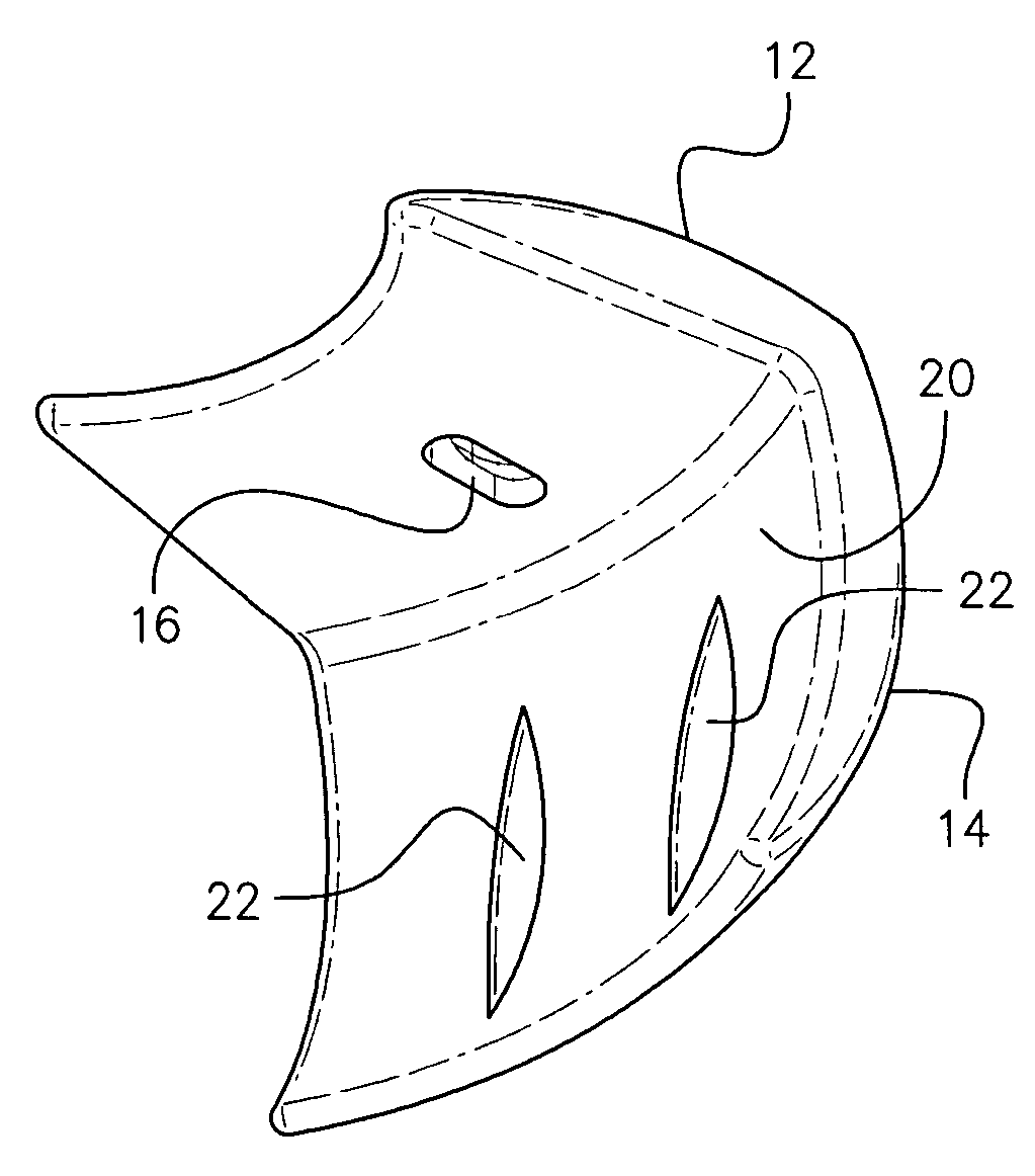
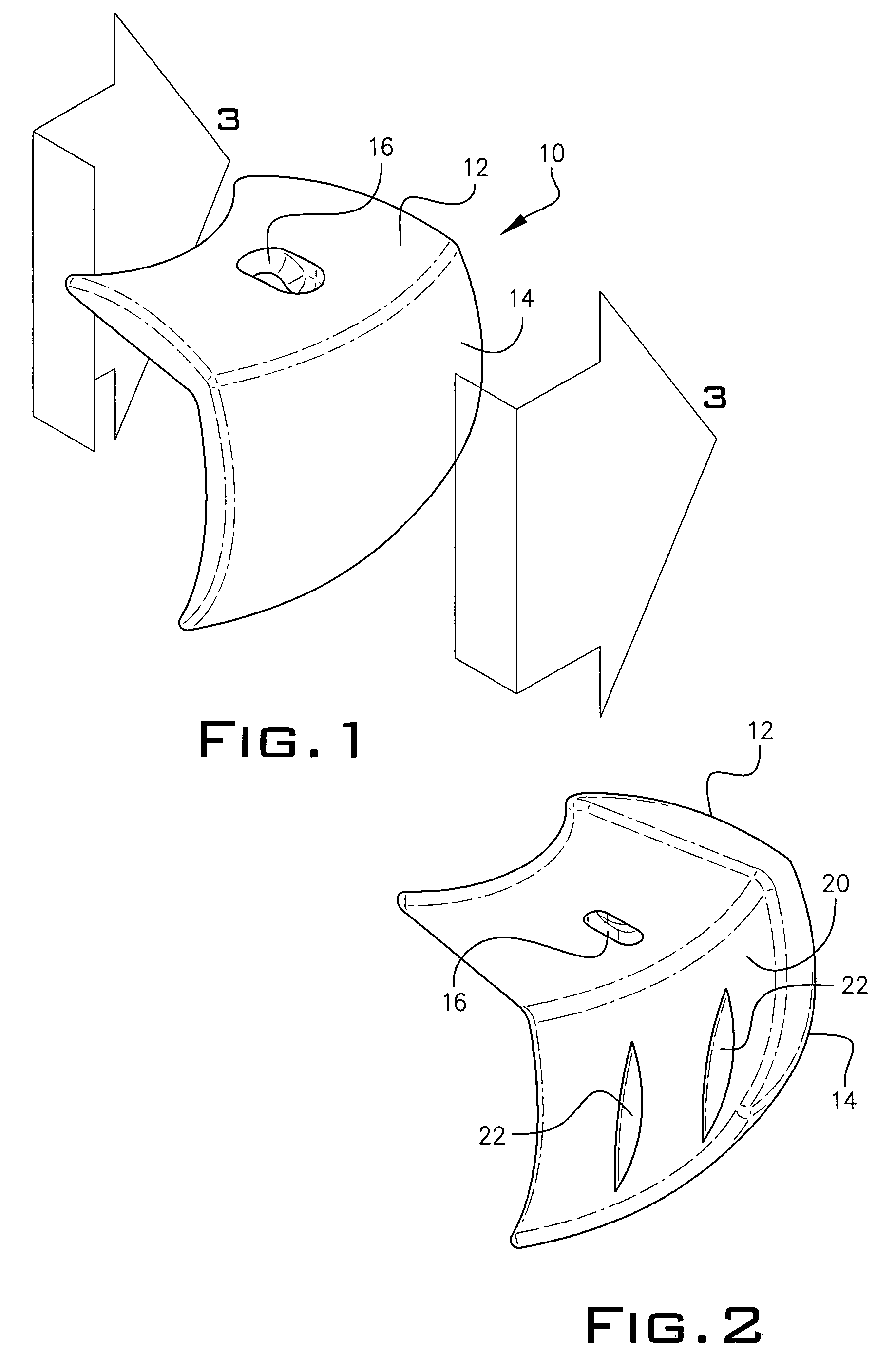
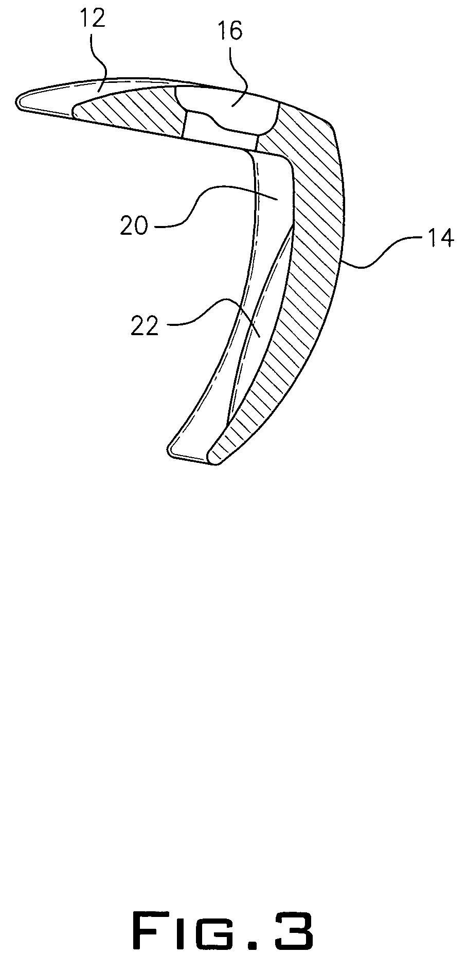
[0016] The minimally invasive a-c joint hemi-arthroplasty implant device 10 disclosed herein is shown in FIGS. 1 and 2. The implant 10 appears to look like an inverted “L” with convex top 12 and side 14 portion. The exterior surface of the top 12 and side 14 portion is a highly polished cobalt-chrome alloy, titanium alloy or other biocompatible material that promotes ease of contact in a patient's joint. A hole 16 in the top portion 12 is provided for entry of a locking screw 18 shown in FIGS. 4 and 5. The inner surface 20 of implant 10 forms a concave structure of the top 12 and side portion 14. A pair of blades 22 are attached to the inner surface 20 of the side portion 14.

[0017] Referring to FIGS. 4 and 5, implant 10 is inserted into a patient's damaged joint 24 so that the highly polished exterior surface of side 14 abuts the joint 24. The inside surface 20 of side portion 14 cuts into bone 26 with blade 22. The screw 18 is inserted into hole 16 and screwed into bone 26. As the...


PUM


Abstract

A biocompatible metallic implant apparatus shaped to fit a natural contour of a shoulder joint, the implant having a cobalt-chrome convex outer surface, a porous concave inner surface and blades on the inner surface for insertion into bone. A locking screw through the implant adheres the implant to the shoulder joint.

Description

PRIOR APPLICATIONS [0001] This application is a continuation-in-part from application SER. No. 10 / 992,697, filed Nov. 22, 2004.BACKGROUND OF THE INVENTION [0002] The present invention relates to a metallic prosthetic implant for us in minimally invasive orthopedic acromio-clavicular joint surgery. More particularly, it refers to a minimally invasive arthroscopic type portal or classic open exposure joint hemi-arthroplasty for the right and left acromio-clavicular (hereinafter “a-c”) joints of the shoulder. The surgery employs the metallic prosthetic implant of this invention to resurface the a-c articulated joints using minimally invasive or arthroscopic portal type techniques to prepare the joint for such implantation. [0003] Present surgical solutions available for the millions of people with small joint injuries, disease, degeneration and related dysfunctions are complex. Invasive operations, often requiring resection, are the only alternatives. Such operations greatly alter join...

Claims


Application Information

Patent Timeline
IPC IPC(8): A61F2/40
CPCA61B17/86A61F2/40A61F2002/30168A61F2002/30578A61F2002/30841A61F2002/4088A61F2230/0043A61F2310/00023A61F2310/00029
Inventor PETERSEN, DAVID A.
Owner MINSURG INT
Learn More