
Bi-axial oriented sheath

a technology of axial orientation and sheath, which is applied in the direction of prosthesis, blood vessels, catheters, etc., can solve the problems of increasing the risk of complications at the patient access site, and the inability to deliver a self-expanding prosthesis to the treatment area, and achieves the effect of thin wall

Inactive Publication Date: 2006-05-25
MEDTRONIC VASCULAR INC
View PDF12 Cites 52 Cited by
  • Summary
  • Abstract
  • Description
  • Claims
  • Application Information

AI Technical Summary

Benefits of technology

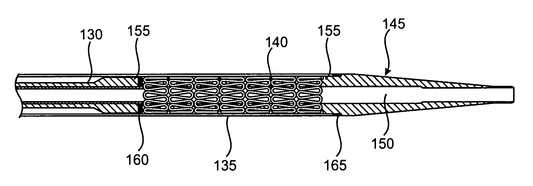
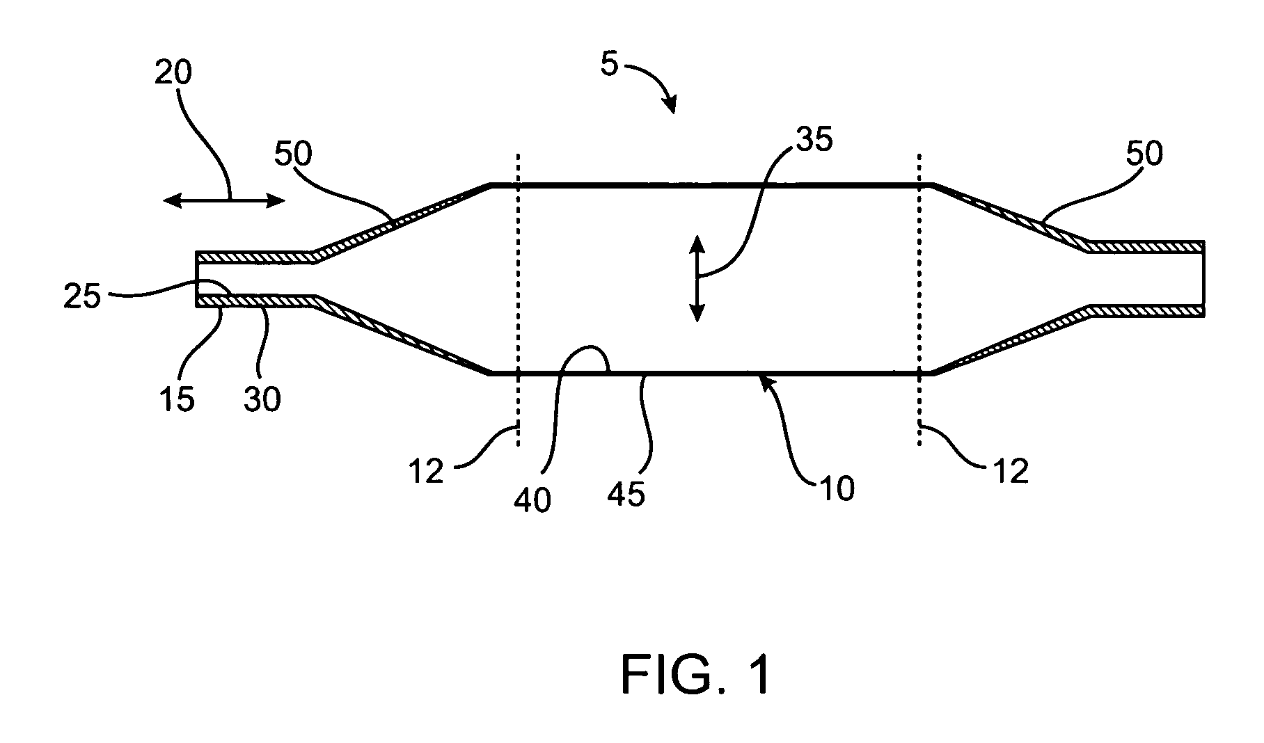
[0006] The invention relates to a sheath used for constraining a self-expanding prosthesis. The sheath is bi-axial oriented and made of high molecular weight polymers. The high molecular weight polymers may include Nylon 12, polyether block amide (PEBAX), polyethylene terephthalate (PET), and polyethylene. One of the advantages of the high molecular weight polymers is that they may withstand a high hoop stress with a thin wall thickness.

Problems solved by technology

The large diameter of the delivery catheter may in turn increase the risk of complications at the patient access site.
The increased cross-sectional profile of the delivery device may make it impossible to deliver a self expanding prosthesis to the treatment area.

Method used


Image

  • Bi-axial oriented sheath
  • Bi-axial oriented sheath
  • Bi-axial oriented sheath

Examples


Embodiment Construction

[0017] Embodiments according to the present invention will find greatest use in the percutaneous placement of a self-expanding prosthesis, such as endovascular stent-grafts and stents, for the treatment of diseases of the vasculature, particularly aneurysms, stenoses, and the like. Graft structures and stents that may be suitable are described in U.S. Pat. Nos. 5,591,195, 5,683,451, 5,824,041 and 6,533,807, the full disclosure of which is incorporated herein by reference.

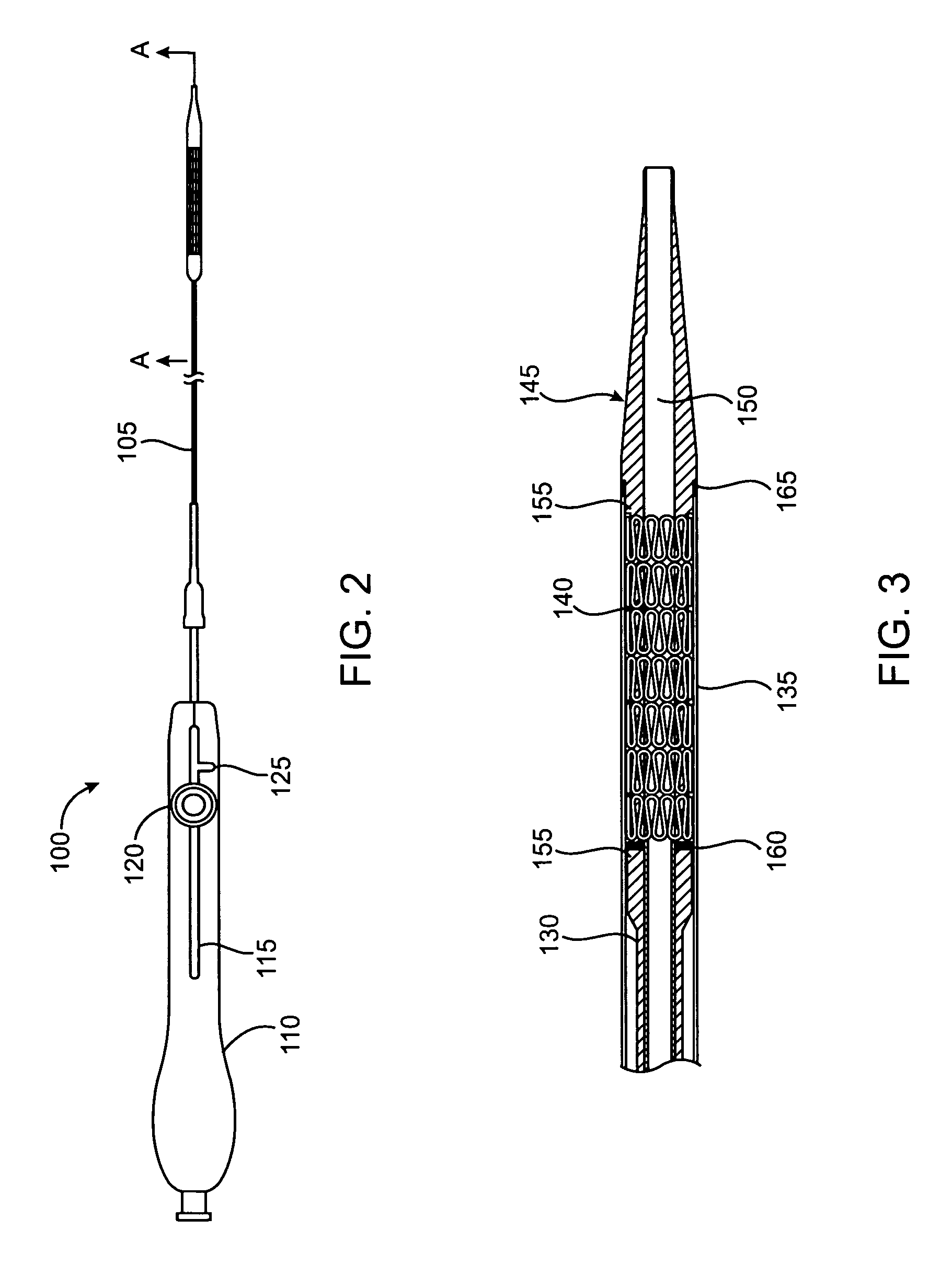
[0018] The self-expanding prosthesis will be radially compressible, and a cover or sheath will maintain the self-expanding prosthesis under compression in a narrow-diameter configuration while they are being introduced to the body lumen, typically during a surgical cutdown or percutaneous introduction procedures. Placement of the self-expanding prosthesis is done by movement (usually retraction) of the sheath, releasing the self-expanding prosthesis at a target location in the vessel. Many of the self-expanding pro...


PUM

PropertyMeasurementUnit
diameteraaaaaaaaaa
diameteraaaaaaaaaa
diameteraaaaaaaaaa

Abstract

A sheath and method of forming is disclosed for a bi-axial oriented made of high molecular weight polymers. The high molecular weight polymers provide a bi-axial oriented sheath with a high hoop stress and a thin wall thickness. A device and method of use is also disclosed for a device for delivery of a self-expanding prosthesis covered by a bi-axial oriented sheath made of high molecular weight polymers. The bi-axial oriented sheath may be moved from a first position constraining the self-expanding prosthesis to a second position releasing the self-expanding prosthesis. During delivery, the device is inserted into the vascular system of the patient, with the self-expanding prosthesis positioned at the location to be treated. The self-expanding prosthesis is then released by moving the bi-axial oriented sheath from the first to second positions, releasing the self-expanding prosthesis.

Description

FIELD OF THE INVENTION [0001] The present invention relates generally to methods and devices for delivering and deploying a self-expanding prosthesis, such as stents, stent-grafts used to treat diseases and conditions of the human vasculature, and more particularly to a bi-axial oriented sheath used to constrain the self-expanding prosthesis. BACKGROUND OF THE INVENTION [0002] Self-expanding prosthesis, such as stents, stent-grafts and other structures, are known in the prior art for maintaining the patency of a diseased or weakened vessel or other passageway. They have been implanted in various body passageways such as blood vessels, the urinary tract, the biliary tract, and other body lumens. These self-expanding prosthesis are inserted into the vessel or passageway, positioned across the treatment area and then are allowed to self expand to keep the vessel or passageway open or protect a weakened area, such as an aneurysm. Effectively, the self-expanding prosthesis overcomes the ...

Claims


Application Information

Patent Timeline
Patent Type & Authority Applications(United States)
IPC IPC(8): A61F2/06
CPCA61F2/95A61F2/966A61L29/041A61L29/06C08L23/06C08L67/00C08L77/00C08L77/12C08L67/02
Inventor MURRAY, ROBERT
Owner MEDTRONIC VASCULAR INC
Learn More