
Method of improving via filling uniformity in isolated and dense via-pattern regions

Inactive Publication Date: 2006-05-25
TAIWAN SEMICON MFG CO LTD
View PDF4 Cites 18 Cited by
  • Summary
  • Abstract
  • Description
  • Claims
  • Application Information

AI Technical Summary

Benefits of technology

[0003] It is an object of the present invention to provide a via filling method to improve filling uniformity in isolated and dense via-pattern regions.
[0005] It is another object of the present invention to provide an isotropic-diffuse filling method using a thermal process on an organic material layer overlying a photoresist layer while simplifying process steps and reducing process costs.
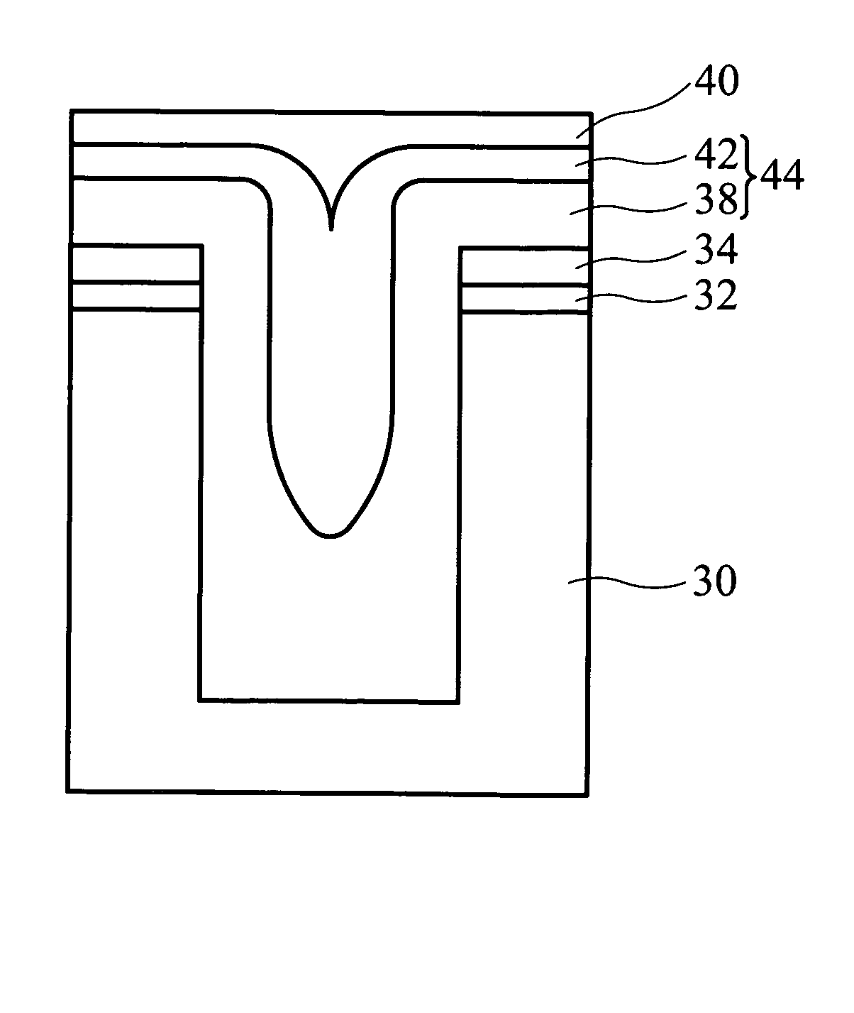
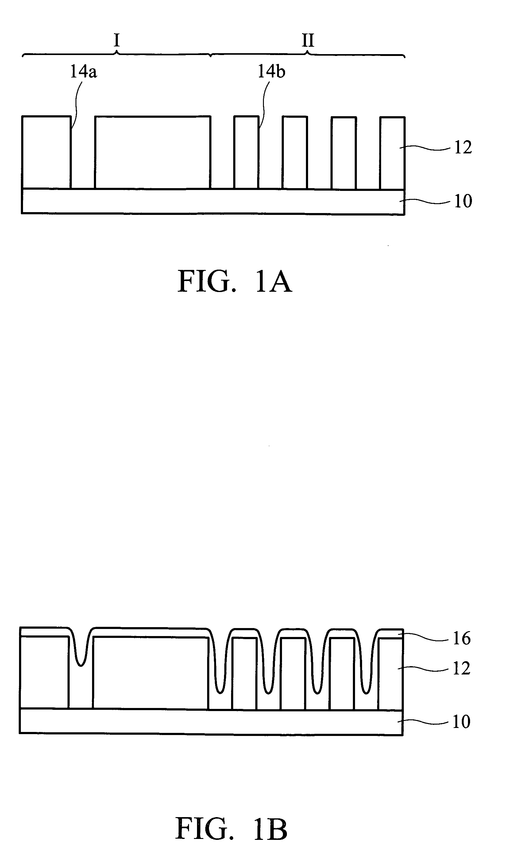
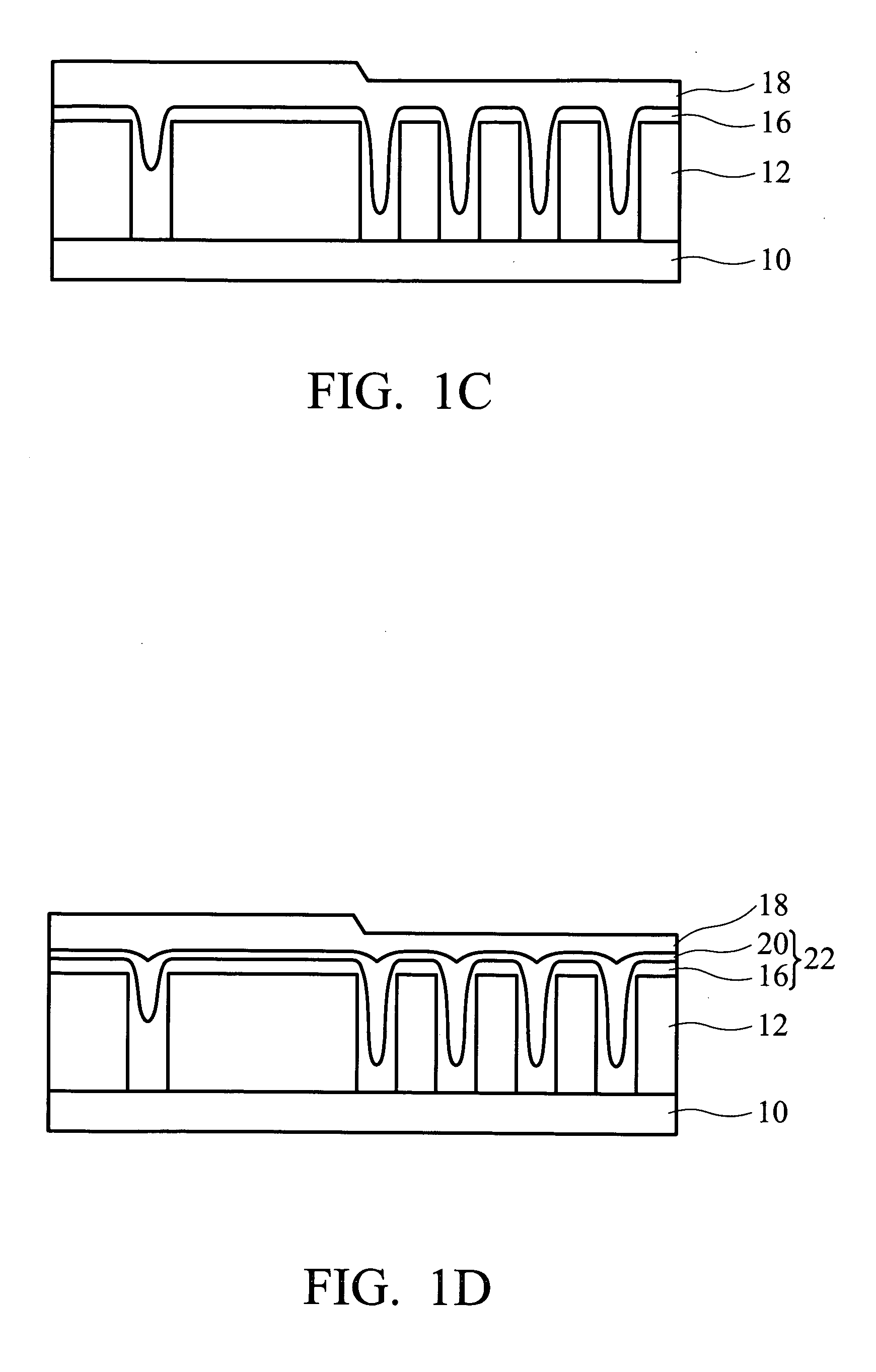
[0007] To achieve the above objectives, the present invention provides a method of filling via openings for reducing step height difference between isolated and dense via-pattern regions. A semiconductor substrate has at least one first via opening in an isolated via-pattern region of a relative low via-pattern density and at least one second via opening in a dense via-pattern region of a relative high via-pattern density. A photoresist layer is formed on the semiconductor substrate to partially fill the first via opening and the second via opening. An organic material is formed on the photoresist layer to completely fill the first via opening and the second via opening. A thermal process is performed to form a cross-linking layer between the organic material layer and the photoresist layer. The cross-linking layer is the reacted portion of the organic material layer. The cross-linking layer combines with the photoresist layer to serve as a sacrificial filling material layer which completely fills the first via opening and the second via opening and minimizes the step height difference between the isolated via-pattern region and the dense via-pattern region. The unreacted portion of the organic material layer is removed from the sacrificial filling material layer.

Problems solved by technology

It is always challenging to optimize the subsequent trench recipe due to uneven filling of the iso-dense via plugs, thus the trench is incompletely etched leaving a fence of unetched resinous material around the via plug.
In one approach to the problem of step height differences in the iso-dense via plugs, an extra step of etch back is needed to minimize the iso-dense via filling variation of organic materials, but complex procedures and high process costs are accompanied.

Method used


Image

  • Method of improving via filling uniformity in isolated and dense via-pattern regions
  • Method of improving via filling uniformity in isolated and dense via-pattern regions
  • Method of improving via filling uniformity in isolated and dense via-pattern regions

Examples


Embodiment Construction

[0013] The present invention provides an isotropic-diffusion filling method using a thermal process on a result structure comprising an organic material layer and a photoresist layer to create a cross-linking layer there between, which minimizes the step height difference between isolated and dense (iso-dense) via-pattern regions for optimizing a subsequent trench process and overcomes the aforementioned problems of the prior art arising from the use of one or more etch back processes. As will be appreciated by persons skilled in the art from discussion herein, one application is used for a dual damascene process, preferably a via-first dual damascene process. The other application is used for a deep trench process, preferably a bottle-shaped trench process.

[0014] Hereinafter, reference will now be made in detail to the present preferred embodiments of the invention, examples of which are illustrated in the accompanying drawings. Wherever possible, the same reference numbers are us...


PUM


Abstract

An isotropic-diffusion filling method uses a thermal process on a result structure comprising a photoresist layer and an organic material layer to create a cross-linking layer there between, which minimizes step height differences between isolated and dense via-pattern regions for optimizing a subsequent trench process and simplifying process steps.

Description

FIELD OF THE INVENTION [0001] The present invention relates to fabrication of integrated circuits and other electronic devices, and particularly to an isotropic-diffuse via filling method for improving via filling uniformity in isolated and dense via-pattern regions. BACKGROUND OF THE INVENTION [0002] Microelectronic integrated circuits (ICs) based on patterned semiconductor materials are continuing to evolve towards devices with an extremely high density of circuit elements per unit volume. The use of copper (Cu), with twice the conductivity of aluminum and three times the conductivity of tungsten, has been replaced as the interconnect material in advanced ICs manufacture using either single inlay or dual damascene processes. The conventional method of patterning trenches in a via-first dual damascene process involves filling via openings with an organic bottom anti-reflective coating (BARC), applying a photoresist layer on the via plug and then performing trench lithography, but a...

Claims


Application Information

Patent Timeline
IPC IPC(8): H01L21/31
CPCH01L21/312H01L21/76808H01L23/5329H01L2924/0002H01L2924/00H01L21/02164H01L21/02126
Inventor YEN, YUNG-SUNGCHEN, KUEI-SHUNLIN, CHIA-HSIANGLIN, LAWRENCELIN, T. H.
Owner TAIWAN SEMICON MFG CO LTD
Learn More