
Self-ligating bracket for use in orthodontics

a self-ligating bracket and orthodontic technology, applied in the field of self-ligating brackets for orthodontic use, can solve the problems of limiting the maximum dimension, weakening the clip, and inability to remedy disadvantages, etc., to facilitate the process of finding the groove, improve the wearing comfort in the mouth, and reduce the overall height of the brack

Active Publication Date: 2006-05-25
BERNHARD FOERSTER GMBH 75172 PFORZHEIM DE
View PDF5 Cites 35 Cited by
  • Summary
  • Abstract
  • Description
  • Claims
  • Application Information

AI Technical Summary

Benefits of technology

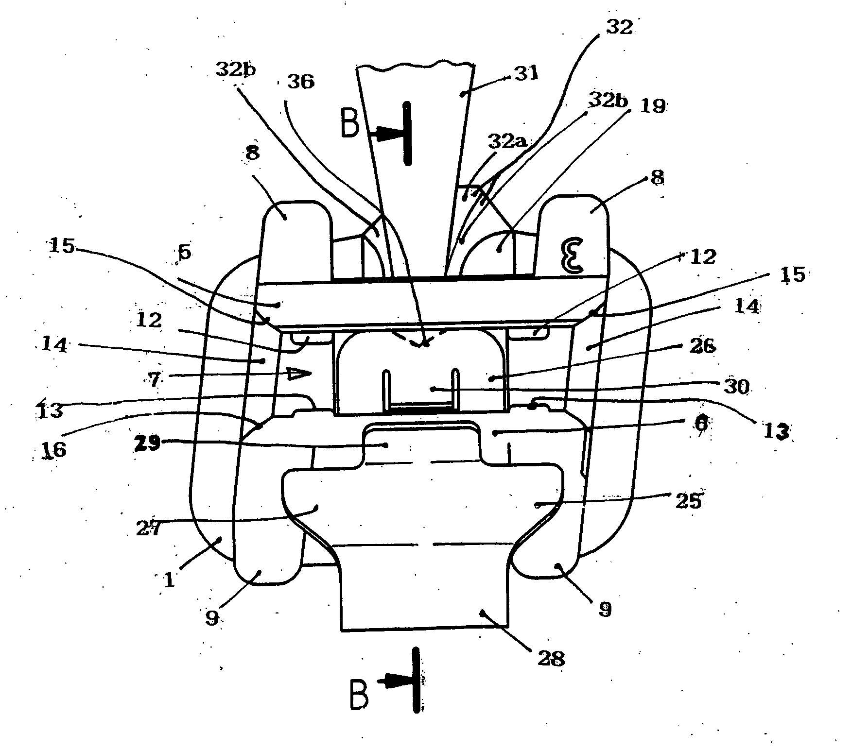
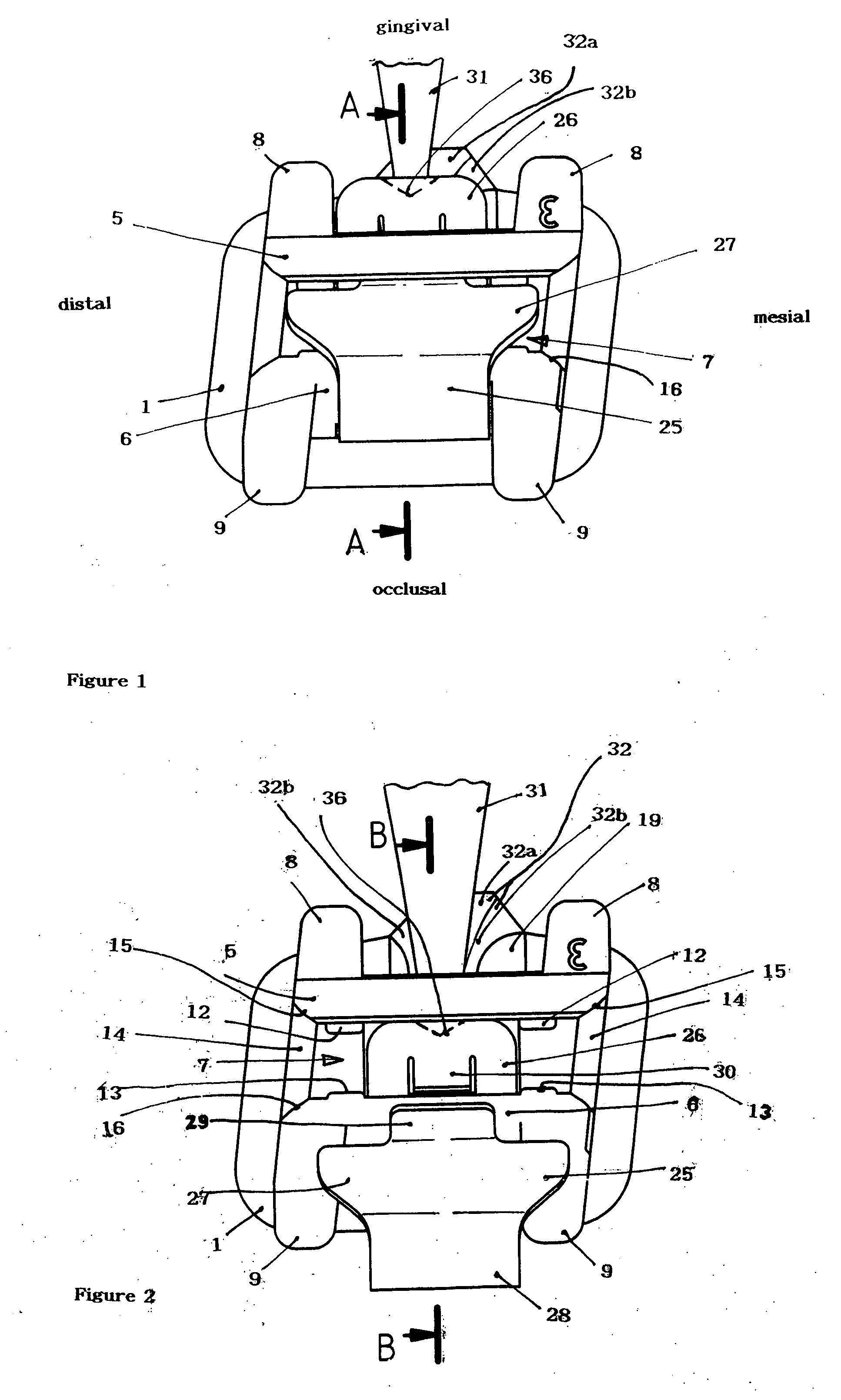
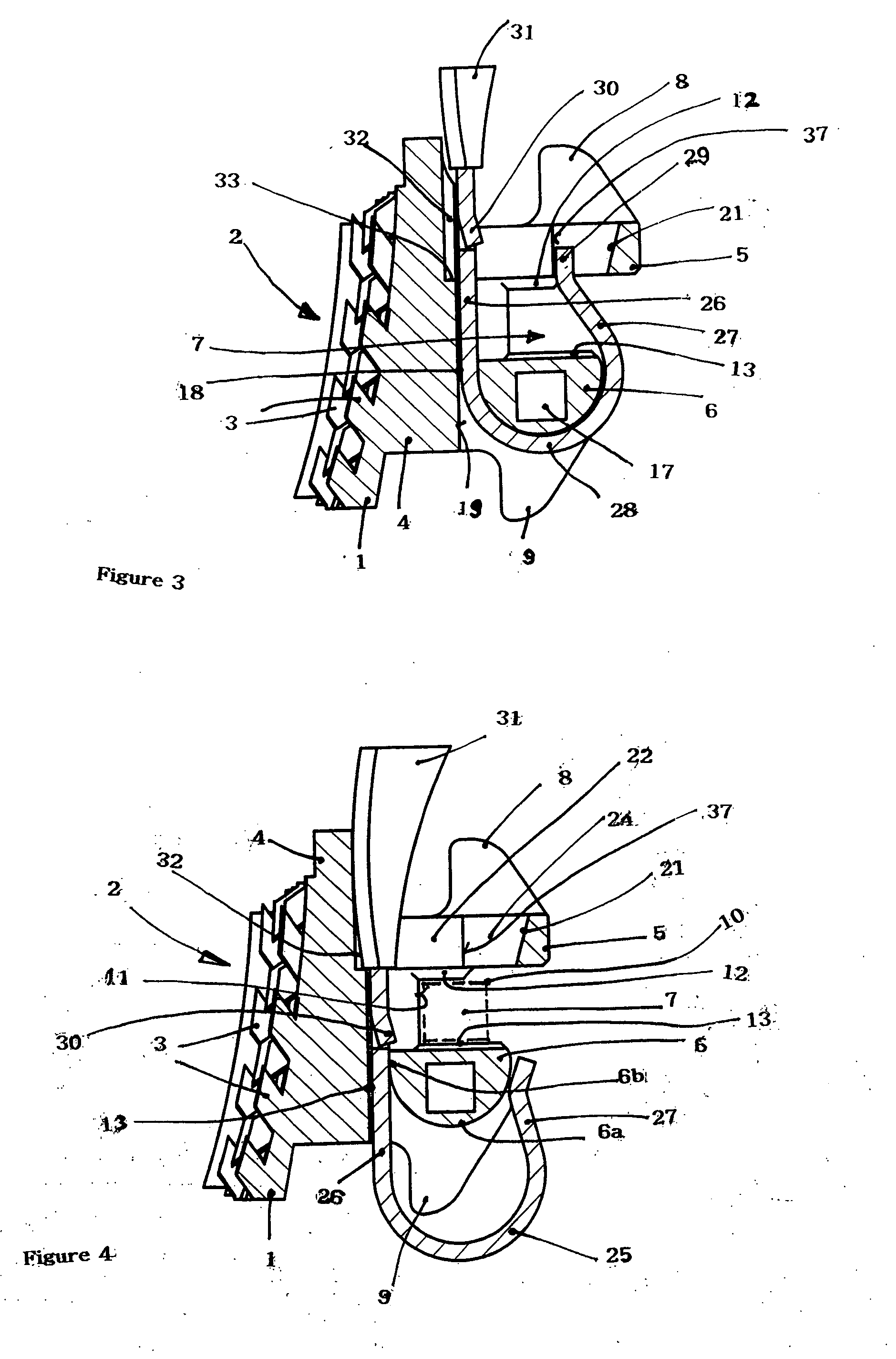
[0021] Such a tongue protects the clip from getting lost during transfer to its open position because, being directed toward the occlusal wall, the tongue will hit against the occlusal wall and be blocked when an attempt is made to move the clip beyond its open position during transfer to its open position from its closed position. Moving the lingual leg of the clip completely out of the second slot, thereby fully detaching the clip from the bracket, will be possible only by pushing the tongue back into the recess in the lingual leg of the clip and simultaneously pressing on the gingival end of the that leg of the clip, or pulling at the occlusal section of the clip. This cannot happen unintentionally. For pressing down the tongue, a tool, for example a pin or a scaler, must be inserted into the second slot from the labial direction. When sliding the clip onto the bracket the tongue will not be felt as an obstacle because it is introduced into the second slot with that end first which foots on the clip, being thus pushed into the recess in the lingual leg of the clip automatically. Consequently, the lingual leg of the clip can be introduced into the second slot of the bracket even more easily than the embossed lingual leg of the clip of the self-ligating bracket known from U.S. Pat. No. 5,906,486 A.
[0038] Preferably, the groove extends in the base of the bracket, at least in part. This is favorable with a view to achieving a small overall height of the bracket which in turn improves the wearing comfort in the mouth. To further the small overall height, the bracket preferably is formed as a single piece. In the case of metal brackets according to the prior art the base frequently is made as a separate part and is connected with the support of the bracket by welding in a second step. According to the invention it is, however, preferred to form the bracket as a single piece, especially by metal injection molding (MIM), a method for the powder-metallurgical production of metallic molded parts related to the injection molding process. With the aid of that method, it is possible to simultaneously form alternately oriented undercut projections on the lower surface of the base of the bracket, which when the bracket is glued onto a tooth lead to clearly improved adhesion of the bracket to the tooth compared with conventional brackets where a wire grating is welded to the lower surface of the base of the bracket. The bonding strength that can be achieved with the aid of the undercut projections is higher by approximately 30% than with brackets provided with a wire grating on their bottom surface. As to the configuration of such undercut projections on the lower surface of the base, reference is made to WO 96 / 09015 A1. The higher bonding strength achievable in this case is of particular advantage in the case of the present invention because in reduces the risk of the bracket being detached from the tooth by the force applied for displacing the clip from its closed position to its open position and by the tool used for this purpose hitting against the bracket.

Problems solved by technology

Further, the stop in the gingival wall of the bracket limits the maximum dimension of the arch wire in the lingual-to-labial direction.
On the one hand, it weakens the clip.
This disadvantage cannot be remedied by an increase in size of the clip because there exists a simultaneous demand that the bracket should be as small as possible.
On the other hand, food particles may easily get into the space between the clip and the occlusal wall, through the hole in the clip, and may even be compacted by the chewing process.
The food particles practically cannot be removed by usual tooth-cleaning methods, which is detrimental in terms of oral hygiene.
The force required for sliding the embossed tip of the lingual leg of the clip through the slot may, however, very well be applied when transferring the clip to its open position so that there actually exists a risk of the clip getting lost or of the patient swallowing it.
This would be different for pressure acting on the labial leg of the clip, as in this case the clip might be damaged, or the tool may slip off and may injure the patient.

Method used


Image

  • Self-ligating bracket for use in orthodontics
  • Self-ligating bracket for use in orthodontics
  • Self-ligating bracket for use in orthodontics

Examples


Embodiment Construction

[0054] The bracket is provided with a curved base 1 the curvature of which is approximated to the front of a tooth. The bottom surface 2 of the base 1, which forms the lingual side of the bracket, is provided with undercut projections 3 arranged in series. The projections are rhomb-shaped in the cross-section shown in FIGS. 3 and 4, and are rectangular in a cross-section taken in parallel to the bottom surface 2. In order to glue the bracket onto a front of a tooth, an adhesive may be applied on the bottom surface 2. Due to the interleaving between the projections 3 and the adhesive good bonding strength is achieved. The projections 3 and, together with them, the undercuts are equally orientated in each row. Between the rows they are, however, alternately oriented in one and the other direction. This has the effect that when a force is applied on the bracket in the gingival-to-occlusal direction the same bonding strength will be achieved as in the case of a force acting in the occlu...


PUM


Abstract

The invention is a self-ligating bracket for use in orthodontics having a base (1); a support (4) arranged on the base (1); an occlusal wall (6) with at least one occlusal ligature wing (9) extending from the support (4); a gingival wall (5) with at least one gingival ligature wing (8) extending from the support (4); a slot (7) separating the occlusal wall (6) and the gingival wall (5) one from the other and extending continuously in the mesial-to-distal direction; a second slot (18) which extends continuously through the support (4) in the gingival-to-occlusal direction, and which is limited by a lingual surface (19) and by a labial surface (6a); and a resilient clip (25) having a labial leg (27) and a lingual leg (26) that are connected one to the other by an occlusal section (28); the lingual leg (26) being received in the second slot (18) and being arranged for displacement in the slot in the gingival-to-occlusal direction between a closed position in which the labial leg (27) extends into a recess (24) in the gingival wall (5) and an open position of the clip (25) in which the tip of the labial leg (27) rests on the occlusal wall (6). A tongue (30), directed toward the occlusal wall (6), is cut out from the lingual leg (26) of the clip (25) and is bent off in the labial direction so that an acute angle is enclosed between the tongue and the lingual leg (26) of the clip (25).

Description

BACKGROUND OF THE INVENTION [0001] 1. Field of the Invention [0002] The present invention related to a self-ligating bracket for use in orthodontics. [0003] 2. Description of Related Art [0004] A bracket of this kind has been known from U.S. Pat. No. 5,906,486. The known bracket comprises a base the bottom of which is prepared for being glued onto a tooth. The base carries a support which has a surface area generally smaller than the base. An occlusal wall and a gingival wall extending from the support include between them a groove which is open in the labial direction and which extends continuously from the mesial to the distal end, separating the occlusal wall and the gingival wall one from the other. In German technical language, just as in the English language, the groove is also described as “slot”. It serves to receive an arch wire which usually runs through a succession of brackets mounted on a series of neighboring teeth. By drawing or twisting the wire a pre-stress can be p...

Claims


Application Information

Patent Timeline
IPC IPC(8): A61C3/00
CPCA61C7/287
Inventor FORSTER, ROLF
Owner BERNHARD FOERSTER GMBH 75172 PFORZHEIM DE
Learn More