
Fabrication of microstructured optical fibre

a technology of optical fibre and microstructure, applied in the field of optical fibre, can solve the problems that the above-specified requirements cannot be met satisfactorily, and achieve the effect of smooth material feed

Inactive Publication Date: 2006-05-18
UNIV OF SOUTHAMPTON
View PDF9 Cites 59 Cited by
  • Summary
  • Abstract
  • Description
  • Claims
  • Application Information

AI Technical Summary

Benefits of technology

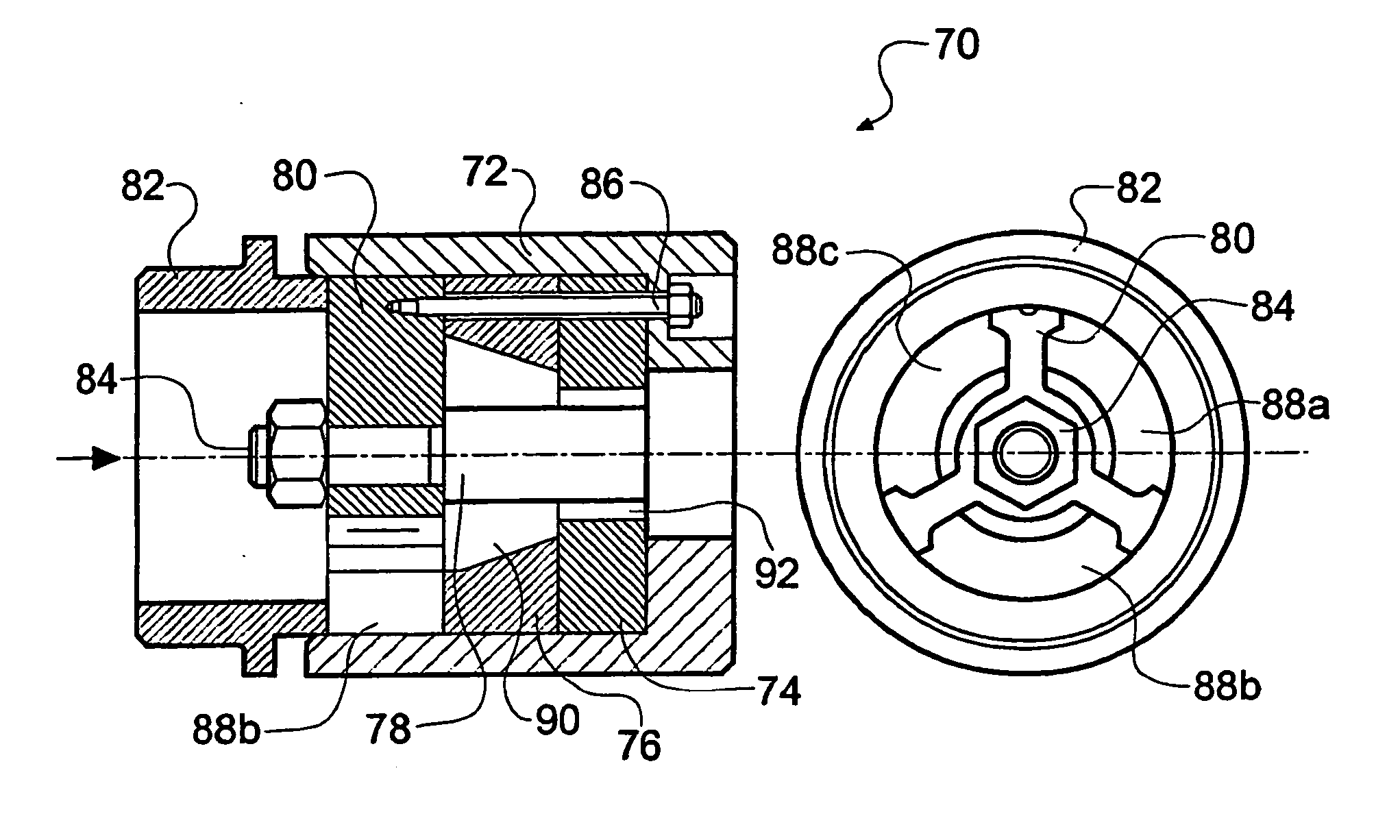
[0030] With this novel die design the multiple requirements for extruding preform shapes required for microstructured optical fibres can be satisfied. In particular, material feed through a central feed channel followed by subsequent diversion of part of the material to fill a welding chamber and continuation of another part of the material to form the central core, allows a high optical quality core to be formed with very smooth surfaces in the core region while at the same time allowing a thick outer wall to be made in combination with thin supporting struts.
[0032] As detailed in the following, the use of extrusion to produce a microstructured preform has been demonstrated. The preform has been caned and drawn into a microstructured optical fibre which is capable of single-moded light guidance over a broad range of wavelengths. The disclosed die design allows extrusion to be used to produce complex structured preforms with good surface quality, and makes efficient use of raw materials. By avoiding capillary stacking, fewer interfaces are involved, and so ultimately extrusion may offer lower losses than existing techniques. In addition, extrusion can be used to produce structures that could not be created with capillary stacking approaches, and so a significantly broader range of properties should be accessible in extruded microstructured fibres. Single-material fibre designs avoid core / cladding interface problems, and so should potentially allow low-loss fibres to be drawn from a wide range of glasses and polymers.
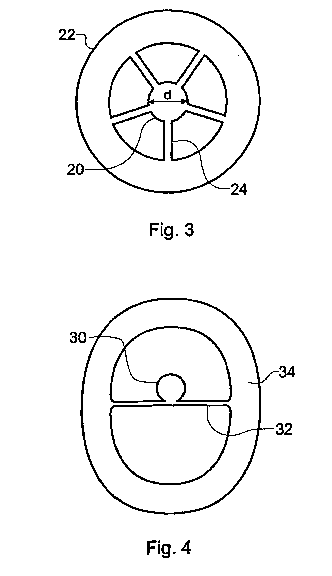
[0034] The mutually facing internal walls may incorporate at least one bend in order to increase the radial length of the struts. This is useful to counteract the effects of surface tension when the preform is reduced by caning and / or drawing. The mutually facing internal walls may extend parallel to each other for a part or the whole of their extent or may be tapered either in the principal flow direction or in a perpendicular plane thereto.
[0037] In other embodiments, the outer part of the nozzle deviates from a circular shape so as to provide sections of preform wall interconnecting wall-to-strut junctions that are shorter than would be required to form a circular-section preform outer wall. This is useful to counteract the effects of surface tension when the preform is reduced by caning and / or drawing and may be advantageously combined with the above-mentioned bends in the internal walls.

Problems solved by technology

It is considered that the above-specified requirements cannot be met satisfactorily with a conventional die design in which the material is forced radially inwardly from a conventional spider feed into a central axial region.

Method used


Image

  • Fabrication of microstructured optical fibre
  • Fabrication of microstructured optical fibre
  • Fabrication of microstructured optical fibre

Examples


first embodiment

[0145]FIG. 15a is a photograph showing an extruded cane preform 160 which has been fabricated using an extruder die 100 according to the first embodiment of the invention described above.

[0146] The cane preform 160 is made from SF57 glass, a commercially available Schott glass. The high lead concentration of this glass leads to a high refractive index of 1.83 at 633 nm and 1.80 at 1.53 μm with losses in the bulk glass of 0.7 dB / m at 633 nm and 0.3 dB / m at 1.53 μm. The non-linear refractive index (n2) measured at 1.06 μm is 4.110−19 W2 / m [4], more than an order of magnitude larger than that of pure silica glass fibres [5]. Since the effective non-linearity of a fibre is γ=n2 / Aeff, where Aeff is the effective mode area. The combination of this glass with the small effective areas (Aeff) possible in micro-structured fibres allows for dramatic improvements in the non-linearity that can be achieved.

[0147] SF57 glass has a low softening temperature (519° C.). The cane preform 160 was ex...

second embodiment

[0159]FIG. 17a schematically shows in vertical section an extruder die 200 for use in manufacturing an optical fibre preform according to a second embodiment of the invention. This particular embodiment is designed to produce a cane preform with greater cross-sectional outer wall thicknesses. In this example, the extruder die 200 is again manufactured from stainless steel grade 303, and is polished to reduce friction. The die 200 comprises an inner die part 202 and an outer die part 204 which together define a welding chamber 206 which is in fluid communication with an opening to the lower face of the extruder die 200.

[0160]FIG. 17b schematically shows in vertical section the outer die part 204. In this example, the outer die part 204 is cylindrically symmetric. The external profile consists of a tapered cone 208 ending in a parallel diameter 210. The inner profile consists of a parallel bore 212 of suitable diameter to mate with the inner die part 202 and which terminates in a tap...

third embodiment

[0165]FIG. 18a schematically shows in vertical section an extruder die 800 for use in manufacturing an optical fibre preform according to a third embodiment of the invention. This particular embodiment is designed to produce a cane preform in which the central core is hollow. In this example, the extruder die 800 is again manufactured from stainless steel grade 303, and is polished to reduce friction. The die 800 comprises an inner die part 802 and an outer die part 804 which together define a welding chamber 806 which is in fluid communication with an opening to the lower face of the extruder die. The extruder die 800 further comprises a spider disc 805 and a mandrel 803.

[0166]FIG. 18b schematically shows in vertical section the outer die part 804. In this example, the outer die part 804 is cylindrically symmetric. The external profile consists of a tapered cone 808 ending in a parallel diameter 810. The inner profile consists of a parallel bore 812 of suitable diameter to mate wi...


PUM

PropertyMeasurementUnit
Lengthaaaaaaaaaa
Lengthaaaaaaaaaa
Lengthaaaaaaaaaa

Abstract

Microstructured optical fibre is fabricated using extrusion. The main design of optical fibre has a core suspended in an outer wall by a plurality of struts. A specially designed extruder die is used which comprises a central feed channel, flow diversion channels arranged to divert material radially outwards into a welding chamber formed within the die, a core forming conduit arranged to receive material by direct onward passage from the central feed channel, and a nozzle having an outer part in flow communication with the welding chamber and an inner part in flow communication with the core forming conduit, to respectively define an outer wall and core of the preform. With this design a relatively thick outer wall can be combined with thin struts (to ensure extinction of the optical mode field) and a core of any desired diameter or other thickness dimension in the case of non-circular cores. As well as glass, the extrusion process is suitable for use with polymers. The microstructured optical fibre is considered to have many potential device applications, in particular for non-linear devices, lasers and amplifiers.

Description

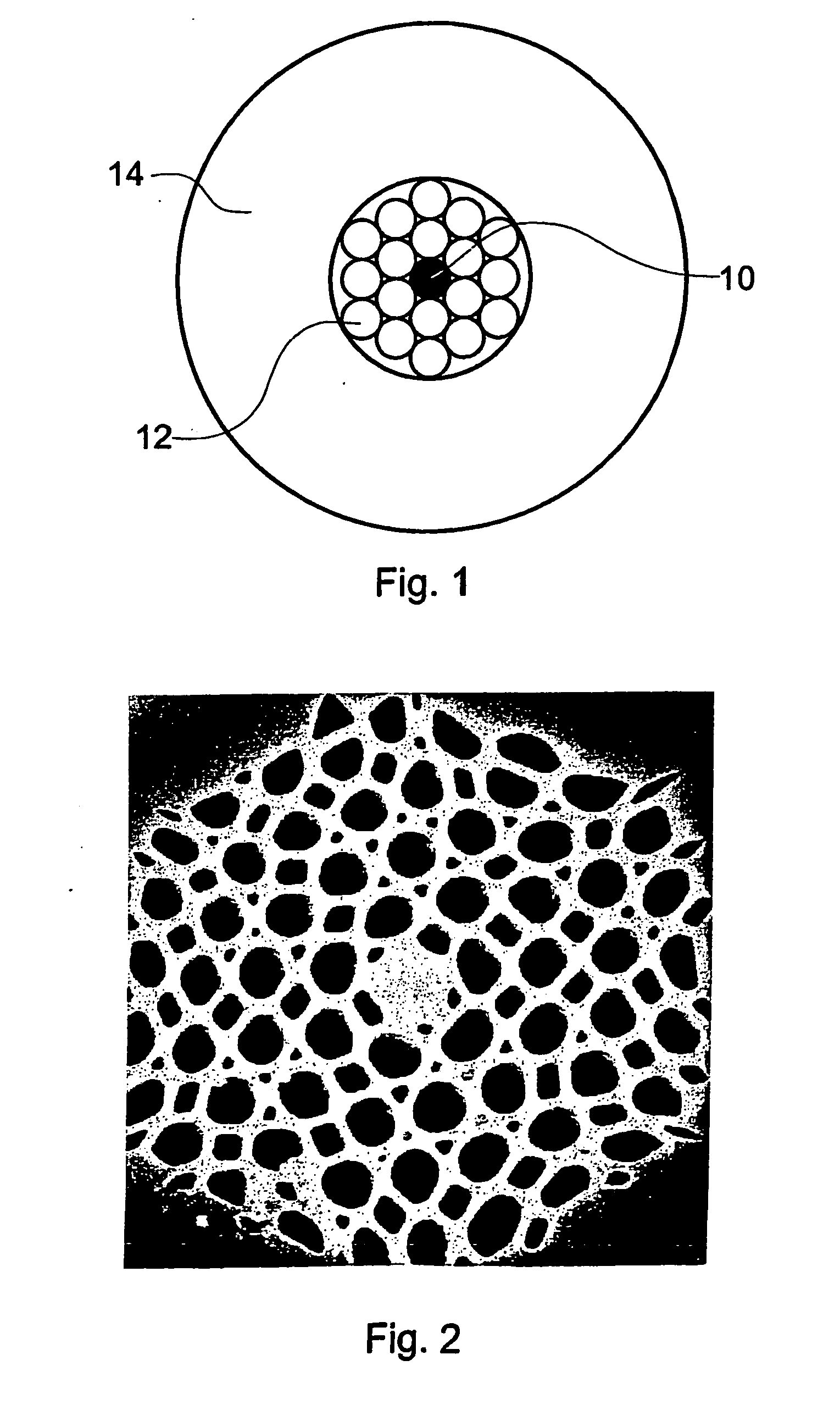
BACKGROUND OF THE INVENTION [0001] The invention relates to optical fibre, more particularly to a process for fabricating microstructured optical fibre, its preforms, to microstructured optical fibre made using the process and to devices incorporating microstructured optical fibre. [0002] Microstructured optical fibre, also frequently referred to in the art as holey fibre or photonic crystal fibre, is the subject of intensive research and development. [0003] To date, microstructured optical fibre has been manufactured by a capillary stacking process. A number of circular section rods are stacked together inside a jacket and drawn or “caned” into a preform. The preform is then drawn again into the microstructured optical fibre. [0004]FIG. 1 of the accompanying drawings is a schematic section of a conventional microstructured fibre preform. A core rod 10 (shown as solid, but may be hollow) is surrounded by at least one ring of hollow cladding capillary tubes 12 (two rings in the figur...

Claims


Application Information

Patent Timeline
IPC IPC(8): G02B6/02B29C48/11B29C48/32B29D11/00C03B37/012C03B37/027H01S3/067H01S3/30
CPCB29C47/0028B29C47/12B29D11/00663B29L2011/0075B29L2031/60B82Y20/00C03B37/0122C03B37/0124C03B37/01274C03B37/027C03B2201/28C03B2201/30C03B2201/31C03B2201/60C03B2201/82C03B2201/86C03B2201/88C03B2203/10C03B2203/12C03B2203/14C03B2203/16C03B2203/18C03B2203/42C03B2205/09C03B2205/10G01N21/552G02B6/02347G02B6/02357G02B6/02371G02B6/02385G02B6/0239H01S3/06708H01S3/06741H01S3/302C03B2203/20B29C48/11B29C48/32
Inventor FRAMPTON, KENNETH EDWARDHEWAK, DANIEL WILLIAMKIANG, KAI MINGMONRO, TANYA MARYMOORE, ROGER CHARLESRICHARDSON, DAVID JOHNRUTT, HARVEYTUCKNOTT, JOHN ANTHONY
Owner UNIV OF SOUTHAMPTON
Learn More