
Laser processing machine and laser processing method

a laser processing machine and laser processing technology, applied in laser beam welding equipment, metal working equipment, manufacturing tools, etc., can solve the problems of difficult to identify the machining position from an image, difficult to correct the section to be machined, critical shifts in the machining position may be caused, etc., to achieve efficient and highly accurate machining of the workpi

Inactive Publication Date: 2006-05-18
HITACHI SEIKO LTD
View PDF1 Cites 37 Cited by
  • Summary
  • Abstract
  • Description
  • Claims
  • Application Information

AI Technical Summary

Benefits of technology

[0005] An object of the present invention is to provide a laser beam machine and a laser machining method that enable, in order to solve the above problems, efficient and highly accurate laser machining of a workpiece with a large number of machining objects arrayed on it, even if the central coordinates of the sections to be machined vary within machining tolerances or the resting positions of the machining objects deviate.
[0021] According to the present invention, efficient and highly accurate machining of a workpiece on which a large number of machining objects are arrayed can be implemented, even if the central coordinates of the sections to be machined vary within-machining tolerances or the resting positions of the machining objects deviate.

Problems solved by technology

However, since micro-size machining objects are narrow in allowable machining region, critical shifts in machining position may be caused if the central coordinates of the sections to be machined vary, even within machining tolerances, or if the resting positions of the machining objects deviate.
If the machining object does not have a specular section, however, the section to be machined has been difficult to correct, because of clear identification being impossible.
In addition, for a machining object with directionality, if the direction of resting is undefined, the direction of the machining object itself must be detected, which has made it impossible to identify a machining position from an image just by evenly illuminating the machining object, even when the position of the object is clearly identifiable with regular light reflections.

Method used


Image

  • Laser processing machine and laser processing method
  • Laser processing machine and laser processing method
  • Laser processing machine and laser processing method

Examples


Embodiment Construction

[0034] Embodiments of a laser beam machine and laser machining method according to the present invention will now be described with reference to the accompanying drawings.

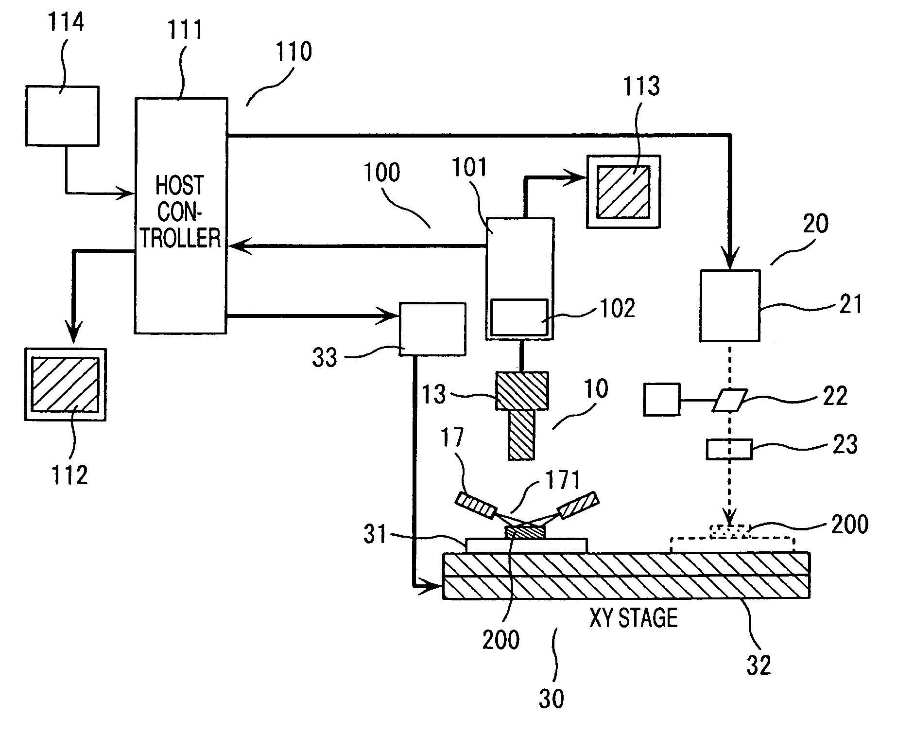
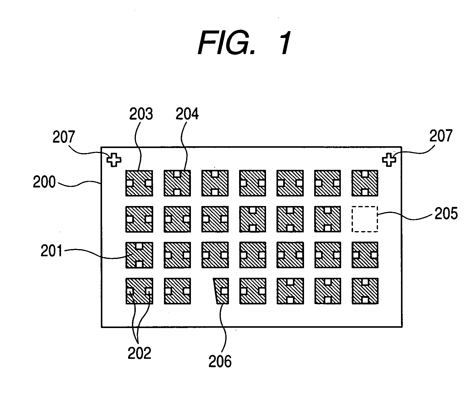
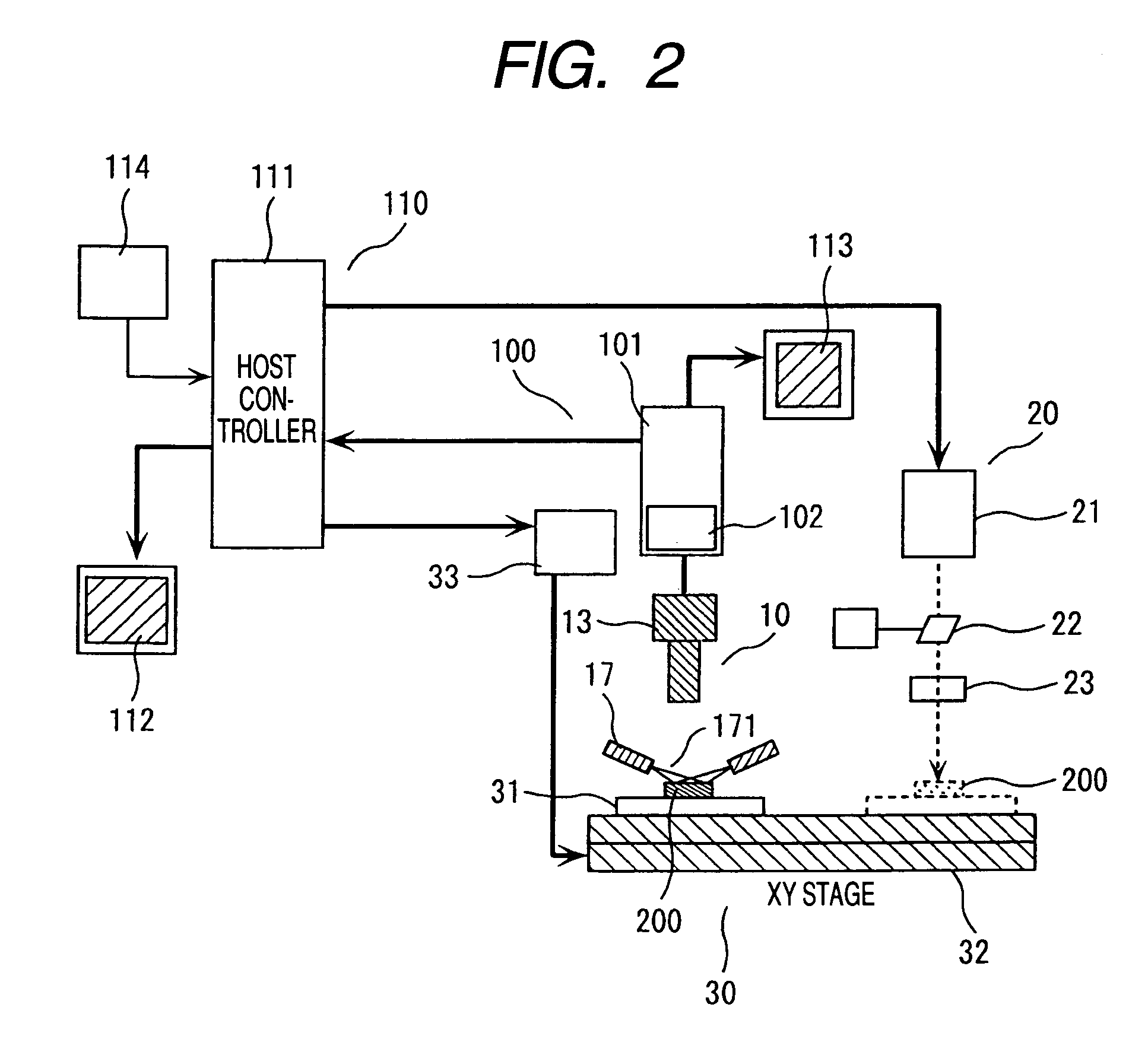
[0035]FIG. 1 is a view showing an example of a workpiece to be machined. FIG. 2 is a configuration diagram that shows an example of a laser beam machine having a machining position correction function in the present invention.

[0036] First, the workpiece to be machined is described below using FIGS. 1 and 7. FIG. 1 shows an enlarged plan view of workpiece 200, and FIG. 7 shows a partially enlarged sectional view of the workpiece. A large number of microchip components 201 with a size of, for example, about 1 mm square, are arrayed and rested on the workpiece 200. The microchip components 201 arrayed on the workpiece is secured to the surface of a sheet 198 of polyimide or the like by means of an adhesive or the like, and the sheet is covered with a protective film 199. Holes for taking antenna-installing terminals...


PUM

PropertyMeasurementUnit
Angleaaaaaaaaaa
Angleaaaaaaaaaa

Abstract

The laser beam machine of the present invention includes: an XY stage on which to rest a workpiece with multiple machining objects arrayed on it, and which moves the workpiece in an XY direction on the basis of NC data; an image acquisition head which is provided in an image acquisition station and has oblique illumination optical system and detection optical system; and a laser machining head which is provided in a laser machining station and has a laser light source, an XY optical beam deflector for deflecting a laser beam in the XY direction on the basis of the deflection control data obtained in accordance with the image signals from each machining object that have been acquired by the image acquisition head, and an irradiation lens for admitting the above-deflected laser beam into each machining object from a substantially perpendicular direction.

Description

BACKGROUND OF THE INVENTION [0001] The present invention relates to a laser beam machine and a laser machining method (a laser processing machine and a laser processing method) that use laser beam irradiation to machine holes in a large number of to-be-machined objects arrayed on a workpiece rested on the XY table numerically controlled. [0002] For conventional laser beam machines of the numerically controlled type, central coordinate design data of the holes to be machined is written into a machining program and these holes are each irradiated with a laser beam in accordance with the machining program (refer to Japanese Patent Laid-Open No. 2000-343260). [0003] In recent years, the miniaturization of the objects to be machined (hereinafter, referred to simply as machining objects) has been accelerated and a large number of batch-rested machining objects are coming to be machined more frequently than before. [0004] However, since micro-size machining objects are narrow in allowable ...

Claims


Application Information

Patent Timeline
IPC IPC(8): B23K26/03B23K26/02B23K26/00B23K26/08
CPCB23K26/03B23K26/032B23K26/04B23K26/0853B23K2201/40B23K26/043B23K2101/40B23K26/02
Inventor KATSUTA, DAISUKENOMOTO, MINEOYOSHIMURA, KAZUSHI
Owner HITACHI SEIKO LTD
Learn More