
Machining device and method for annular bulge of aluminum alloy conduit connector

A technique for conduit joints and processing devices, which is applied in the field of mechanical manufacturing and processing, can solve problems such as unreasonable structure and design, difficulty in meeting the manufacturing requirements of passenger aircraft, and affecting the processing quality and efficiency of aluminum alloy conduit joint ring protrusions, etc., to achieve The processing method is convenient, the structure is simple, and the effect of being easy to manufacture and assemble

Inactive Publication Date: 2014-12-17
SHENYANG AIRCRAFT CORP
View PDF7 Cites 2 Cited by
  • Summary
  • Abstract
  • Description
  • Claims
  • Application Information

AI Technical Summary

Problems solved by technology

However, the existing processing tools and methods for the ring protrusions of aluminum alloy conduit joints have seriously affected the processing quality and efficiency of the ring protrusions of aluminum alloy conduit joints due to their unreasonable structure and design, and are difficult to meet the requirements of manufacturing passenger aircraft. Require

Method used


Image

  • Machining device and method for annular bulge of aluminum alloy conduit connector
  • Machining device and method for annular bulge of aluminum alloy conduit connector
  • Machining device and method for annular bulge of aluminum alloy conduit connector

Examples


Embodiment Construction

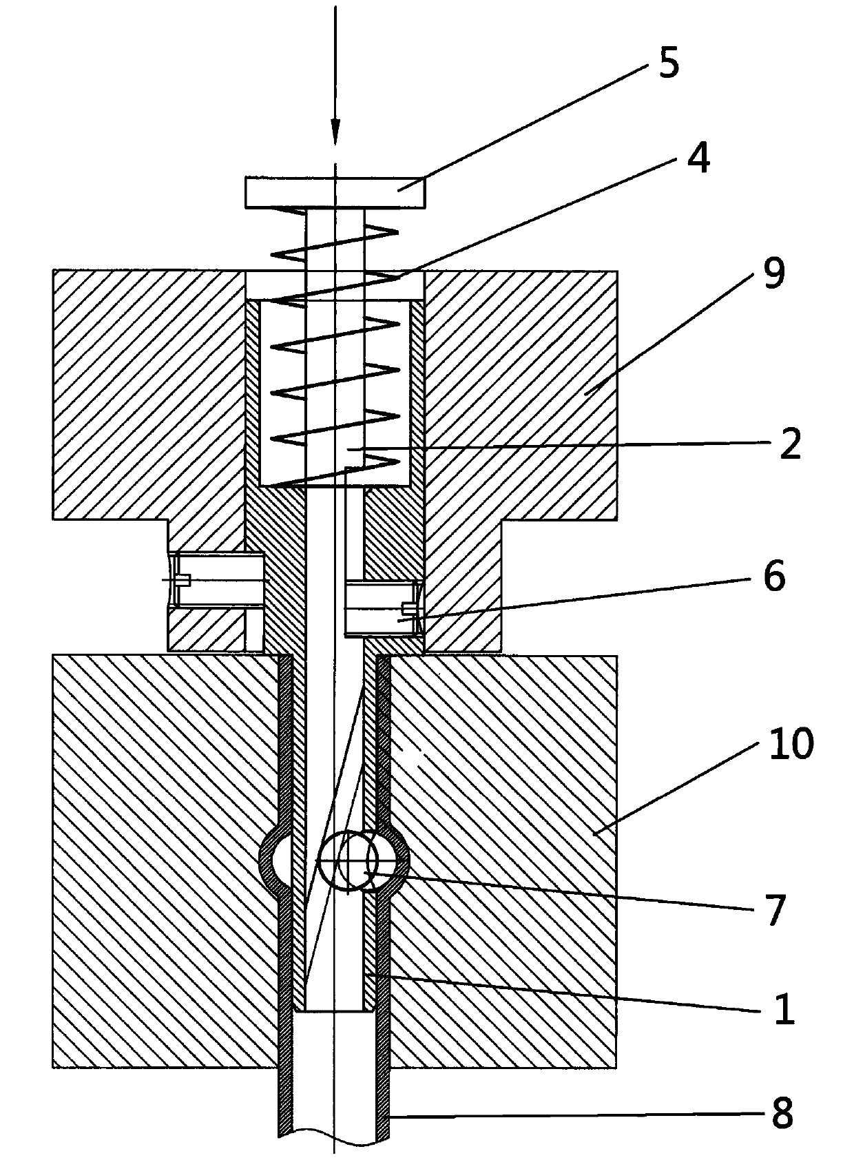
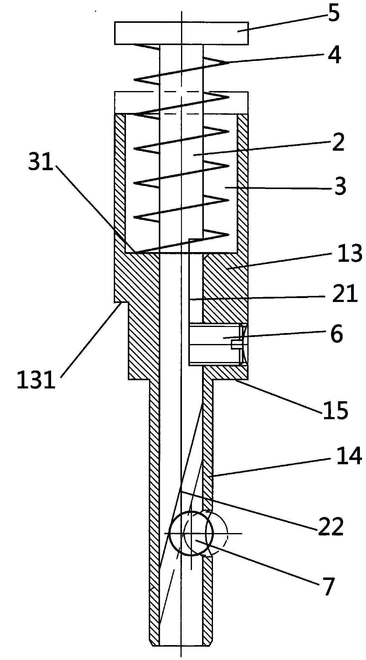
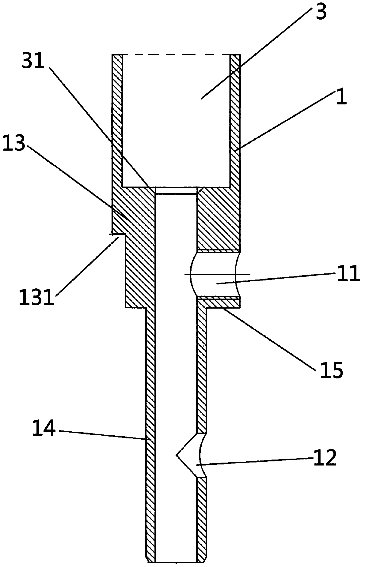
[0025] Such as Figure 1-3 As shown, 1. An aluminum alloy conduit joint ring protrusion processing device has a housing 1, a mandrel 2 placed in the housing 1, a cavity 3 is provided at one end of the housing 1, and a limit spring 4 is placed The concave cavity 3 is sleeved on the mandrel 2, one end of the limit spring 4 is fixedly connected to the bottom 31 of the cavity, and the other end is fixedly connected to the force block 5 at the top of the mandrel 2, and the middle part of the mandrel 2 is provided with Groove 21, the housing 1 corresponding to the groove 21 is provided with an opening I11, the top wire 6 is placed at the opening I11 and fits with the groove 21, the tail end of the mandrel 2 is a slope 22, corresponding to the slope 22 The shell 1 is provided with an opening II12, and the ball 7 is placed at the opening II12 and cooperates with the inclined surface 22.

[0026] Such as image 3 The outer wall of the housing 1 shown is divided into a clamping sectio...


PUM

PropertyMeasurementUnit
thicknessaaaaaaaaaa
sizeaaaaaaaaaa

Abstract

The invention discloses a machining device and a machining method for an annular bulge of an aluminum alloy conduit connector. The device is provided with a shell and a core shaft arranged in the shell, wherein a concave cavity is arranged at one end of the shell and a limiting spring is arranged in the concave cavity and arranged on the core shaft in a sleeving manner; one end of the limiting spring is fixedly connected with the bottom of the concave cavity and the other end of the limiting spring is fixedly connected with a stress application block at the top of the core shaft; a groove is formed in the middle of the core shaft and an opening I is formed in the shell corresponding to the groove; a jackscrew is arranged at the opening I and is matched with the groove; the tail end of the core shaft is an inclined plane; an opening II is formed in the shell corresponding to the inclined plane; a ball is matched with the inclined plane at the opening II. The machining device is simple in structure and convenient to manufacture and assemble; the machining method is convenient to operate and has low requirements on technicists; the efficient and high-precision machining of the annular bulge of the aluminum alloy conduit connector can be realized.

Description

technical field [0001] The invention relates to the field of mechanical manufacturing and processing, and in particular to a device and method for processing ring protrusions of aluminum alloy conduit joints. Background technique [0002] With the development of the mechanical industry, pneumatic and hydraulic power has been more and more widely used in the design of mechanical equipment and aviation products, especially passenger aircraft. Some of the pipelines in the air pressure and oil pressure systems are metal and some are non-metallic. The connection between metal and non-metallic pipelines, especially between metal and flexible hoses, is usually at a certain distance from the end of the metal pipe. Process ring-shaped protrusions to improve connection quality and efficiency, especially for flexible connections of low-pressure system piping, such as hose connections. However, the existing processing tools and methods for the ring protrusions of aluminum alloy conduit...

Claims


Application Information

Patent Timeline
Patent Type & Authority Applications(China)
IPC IPC(8): B21D17/00B21D43/00
Inventor 唐臣升潘国华李宁刘舒红李研
Owner SHENYANG AIRCRAFT CORP
Learn More