Control apparatus and method for vehicle

a technology of control apparatus and transmission device, which is applied in the direction of mechanical apparatus, digital data processing details, instruments, etc., can solve the problems of reducing reducing the fuel efficiency improvement effect, and shortening the period during which the neutral control is executed, so as to reduce the amount of heat generated at the apply element and reduce the durability of the input clutch

Active Publication Date: 2006-05-11
TOYOTA JIDOSHA KK
View PDF9 Cites 8 Cited by
  • Summary
  • Abstract
  • Description
  • Claims
  • Application Information

AI Technical Summary

Benefits of technology

[0019] According to the control apparatus and method for a vehicle as described above, the determination as to whether to execute the neutral control is made not based on the engine speed, which fluctuates in real time as the load of auxiliary devices changes, but rather based on required torque or the like, e.g., a target idle speed calculated by an ISC (Idle Speed Control system) of an engine ECU (Electronic Control Unit). Because the target idle speed does not change as quickly nor as subtly as the engine speed, it is not necessary to set the engine speed at which the neutral control is allowed high. Accordingly, the apply element will not be kept in a state of slip when the engine speed is high so the amount of heat generated will not increase and the durability of the apply element will not be reduced. In particular, by setting the target idle speed threshold value, which is used to determine that the neutral control can not be executed, to a high speed yet in a range where it will not cause problems with the durability of the apply element, it is possible to extend the neutral control period without reducing the durability of the apply element. It is possible that in this case the actual speed may deviate from the target idle speed, but if it does, that deviation would be eliminated quickly by the feedback control on the idle speed by the ISC so that the durability of the apply element would not be reduced. As a result, a control apparatus for a vehicle can be provided that executes neutral control while ensuring the durability of the apply element.
[0021] As described above, this control apparatus and method determines whether to execute the neutral control based on the difference between the engine speed and the target idle speed. When this difference is large, there is a tendency for the engine speed to take more time to reach the target idle speed using the feedback control by the ISC, which may cause problems with respect to the durability of the apply element. Therefore, when the difference is large, it is determined that the neutral control can not be executed so the neutral control is not executed. As a result, a control apparatus for a vehicle can be provided that executes neutral control while ensuring the durability of the apply element. Also, when the difference is large, it is possible that learning control by the ISC has not yet ended. Therefore, when the neutral control is started, the ISC opening is changed in anticipation of a change (i.e., a decrease) in load on the engine. Doing so, however, may result in the change in engine speed being greater than usual, and thus a decrease in drivability. Not executing the neutral control, therefore, enables such a decrease in drivability to be avoided.

Problems solved by technology

When the driver wants a vehicle that is stationary on a flat road to remain in one spot, however, creeping is unnecessary and must be suppressed by operating the brake.
If, as the engine speed fluctuates, it becomes even slightly higher than the set idle speed, the neutral control is cancelled, thus shortening the period during which the neutral control is executed and reducing the fuel efficiency improvement effect.
Increasing the idle speed in the manner, however, results in the neutral control being continued while the engine speed is increased.
This generated heat causes problems such as a reduction in the durability of the input clutch.
As a result, when the engine speed is high, the heat generated by the input clutch slipping increases and causes problems such as a reduction in the durability of the input clutch.
In addition, problems such as a reduction in the durability of the input clutch may also occur if the clutch apply pressure of the input clutch remains high for an extended period of time.

Method used


Image

  • Control apparatus and method for vehicle
  • Control apparatus and method for vehicle
  • Control apparatus and method for vehicle

Examples


Embodiment Construction

[0038] In the following description and the accompanying drawings, the present invention will be described in more detail with reference to exemplary embodiments.

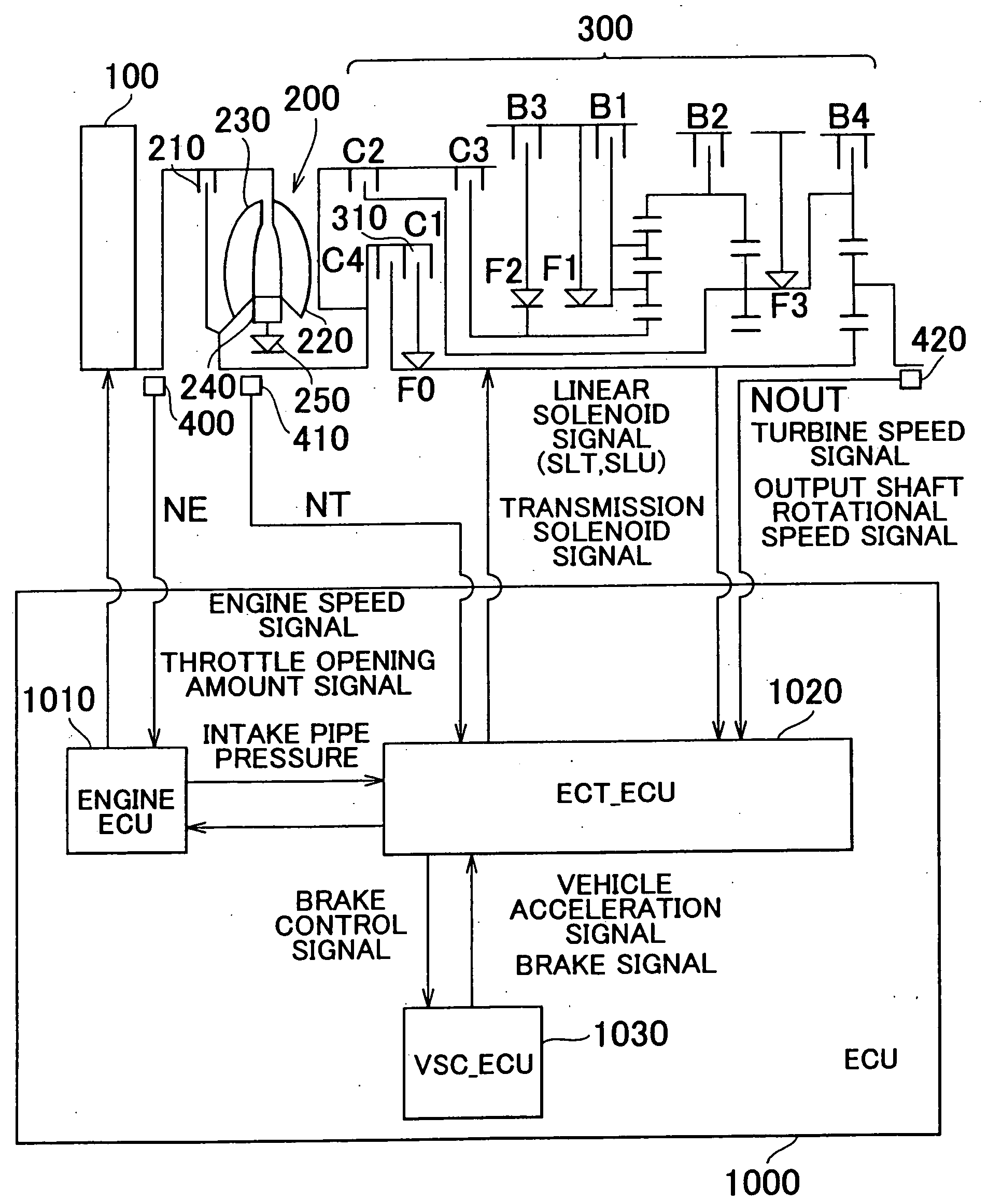
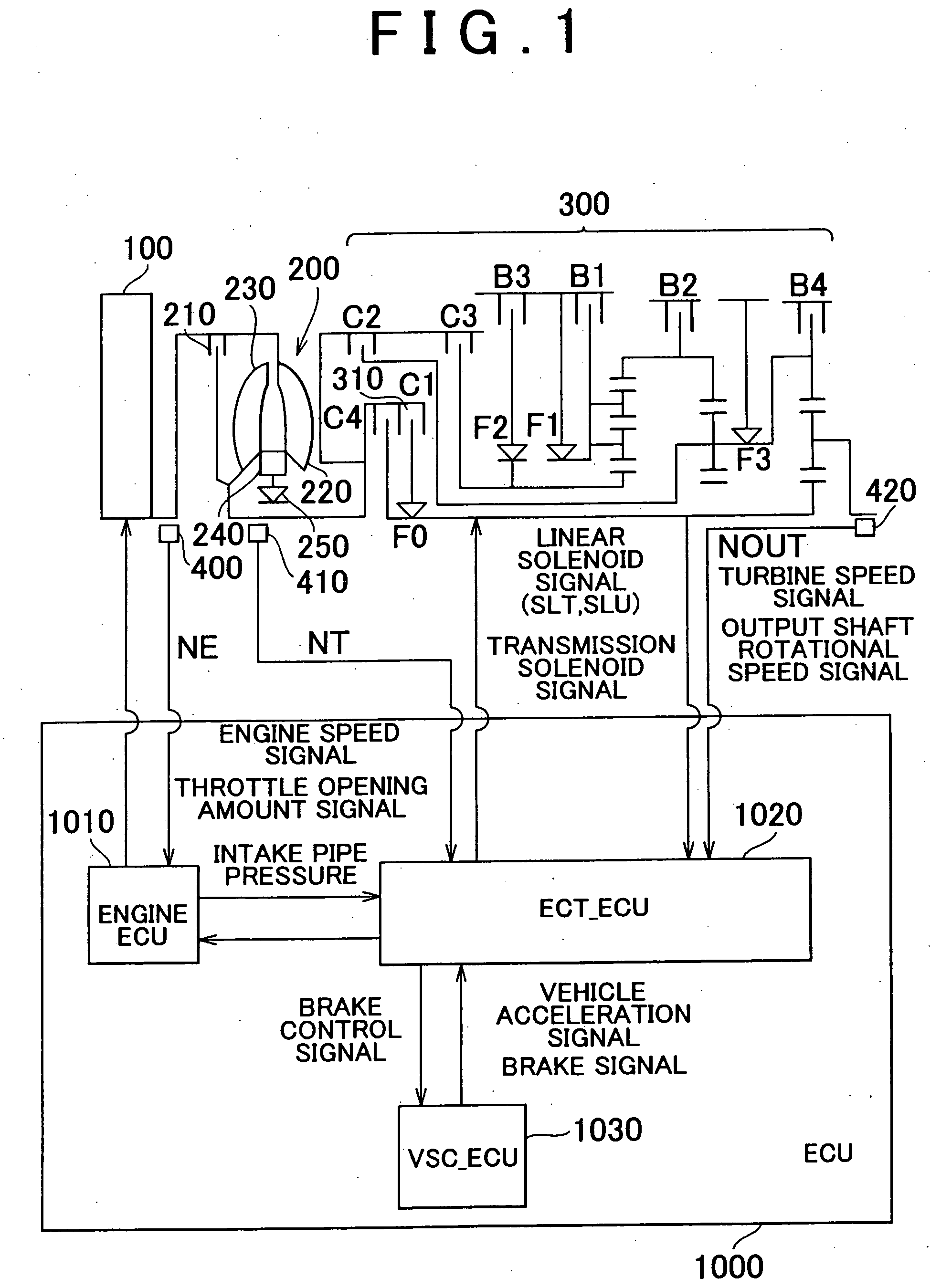
[0039] A power train of a vehicle including a control apparatus according to one exemplary embodiment of this invention is as follows. The control apparatus according to this exemplary embodiment is realized by an ECU (Electronic Control Unit) 1000 shown in FIG. 1. The automatic transmission described in this exemplary embodiment is an automatic transmission that is provided with a torque converter, which serves as a fluid coupling, and a planetary gear type gear change mechanism. It should be noted, however, that this invention is not limited to an automatic transmission having a planetary gear type gear change mechanism. That is, the automatic transmission may also be, for example, a continuously variable transmission such as a belt type continuously variable transmission.

[0040] The power train of a vehicle including a ...


PUM


Abstract

A control apparatus for a vehicle equipped with an automatic transmission having an apply element that is applied when the vehicle takes off from a standstill, which executes a neutral control which releases the apply element when the automatic transmission is in a forward-drive range and the vehicle is stopped with a predetermined condition being satisfied, includes a controller that detects a target idle speed of an engine and determines whether the neutral control can be executed based on the target idle speed.

Description

INCORPORATION BY REFERENCE [0001] The disclosure of Japanese Patent Application No. 2003-197108 filed on Jul. 15, 2003, including the specification, drawings and abstract is incorporated herein by reference in its entirety. BACKGROUND OF THE INVENTION [0002] 1. Field of the Invention [0003] The invention generally relates to a control apparatus and method for a vehicle equipped with an automatic transmission. More particularly, the invention relates to a control apparatus and method for a vehicle which executes a neutral control. [0004] 2. Description of the Related Art [0005] An automatic transmission mounted in a vehicle is connected to an engine via a torque converter or the like provided in the automatic transmission, and includes a gear change mechanism that provides a plurality of power transmission paths. This automatic transmission is structured so as to automatically switch the power transmission path, i.e., the gear ratio (drive speed), based on the accelerator opening amo...

Claims


Application Information

Patent Timeline
Patent Type & Authority Applications(United States)
IPC IPC(8): G06F17/00F16H59/38F16H61/02F16H61/20F16H61/686
CPCF16H61/20F16H2059/385Y10T477/681F16H2061/207F16H2312/02
Inventor MATSUBARA, TOORUHASEGAWA, YOSHIONAGAI, TADAYUKI
Owner TOYOTA JIDOSHA KK
Why Eureka
Try Eureka