Preheating bulk erase device for optical recording medium, preheating bulk erase method for optical recording medium, and optical recording medium
a bulk eraser and recording medium technology, applied in the field of preheating bulk erasers for optical recording mediums, optical recording medium preheating methods, optical recording mediums, etc., can solve the problems of no practical method and a lot of time, and achieve the effect of reducing tracking errors
- Summary
- Abstract
- Description
- Claims
- Application Information
AI Technical Summary
Benefits of technology
Problems solved by technology
Method used
Image

Examples
embodiment 1
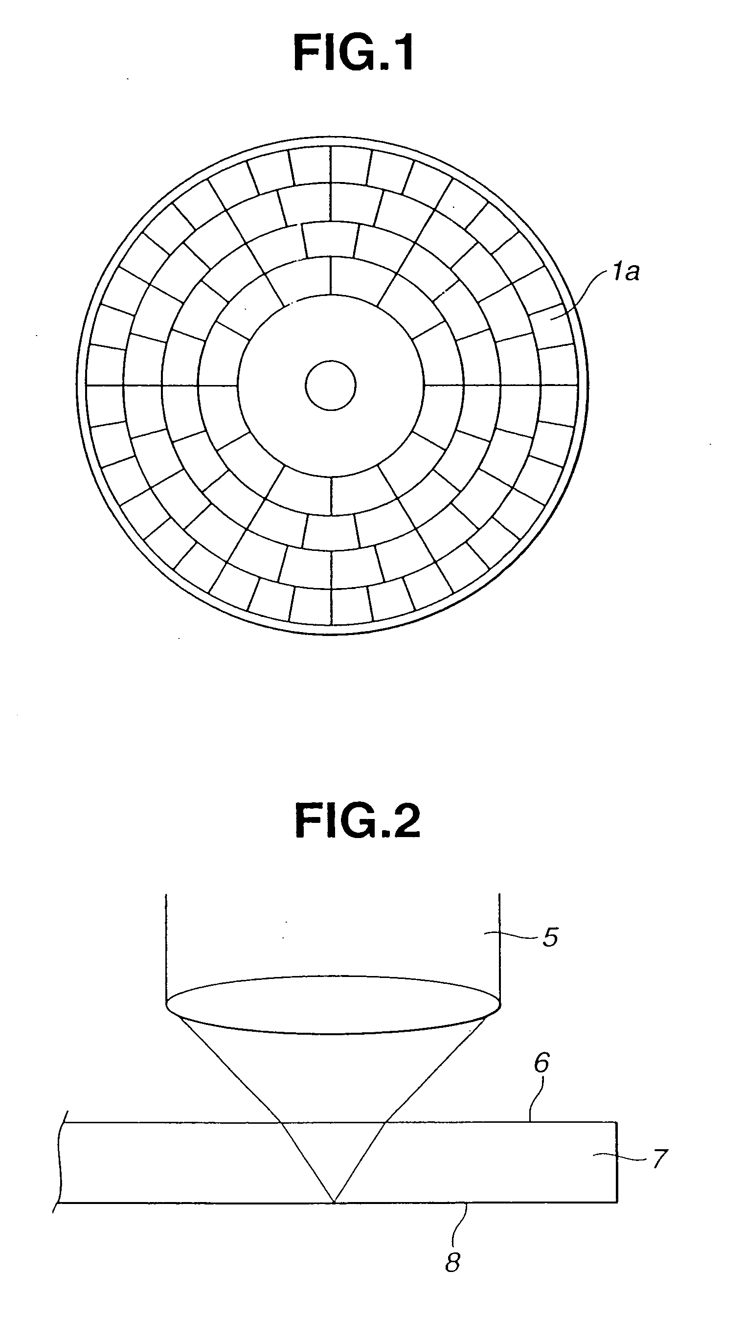
[0057] First of all, we will explain an embodiment using a magneto-optically recordable / reproducible multi-layer recording film. With a section of the used medium, as shown in FIG. 4, for example, a protective layer 10b-1, a magneto-optical recording layer 10c-1-1, 10c-1-2, 10c-1-3, a protective layer 10d-1, and a reflective layer 10e-1 are laminated and formed one upon another by a sputtering method on a resin substrate 10a-1 having an address layout in FIG. 1.
[0058] First, a chamber for sputtering each layer was sufficiently evacuated in advance until the reached degree of vacuum is lower than 10−5 Pa. Then, in the atmosphere of 1×10⁻³ Pa to 6×10⁻³ Pa, each film was formed by a power of 2-3 kW.
[0059] As the protective layer 10b-1, a silicon nitride film of 80 nm was formed by performing reactive sputtering of a silicon target in the atmosphere of argon and nitrogen.
[0060] As the magneto-optical recording layer 10c-1-1, a film was formed to obtain 40 nm film thickness by perform...
embodiment 2
[0087] Next, we will explain an embodiment using a magneto-optically recordable / reproducible single-layer recording film. With a section of the used medium, as shown in FIG. 9, for example, a protective layer 10b-2, a magneto-optical recording layer 10c-2, a protective layer 10d-2, and a reflective layer 10e-2 are laminated and formed one upon another by a sputtering method on a resin substrate 10a-2 having an address layout in FIG. 1.
[0088] First, a chamber for sputtering each layer was sufficiently evacuated in advance until the reached degree of vacuum is lower than 10−5 Pa.
[0089] As the protective layer 10b-2, a silicon nitride film of 100 nm was formed by performing reactive sputtering of a silicon target in the atmosphere of argon and nitrogen.
[0090] As the magneto-optical recording layer 10c-2, a film was formed to obtain 50 nm film thickness by performing DC sputtering of a TbFeCo target in the atmosphere of argon. A composition of the target and a condition of film forma...
embodiment 3
[0096] Next, we will explain an embodiment using a phase-change type recording film. With a section of the used medium, as shown in FIG. 11, for example, a protective layer 10b-3, a phase-change type recording layer 10c-3, a protective layer 10d-3, and a reflective layer 10e-3 are laminated and formed one upon another by a sputtering method on a resin substrate 10a-3 having an address layout in FIG. 1.
[0097] First, a chamber for sputtering each layer is sufficiently evacuated in advance until the reached degree of vacuum is lower than 10−5 Pa.
[0098] As the protective layer 10b-3, a ZnS-SiO2 film of 130 nm was formed by performing sputtering of a ZnS-SiO2 target in the atmosphere of argon.
[0099] As the phase-change type recording layer 10c-3, a film was formed to obtain 15 nm film thickness by performing DC sputtering of a GeSbTe target in the atmosphere of argon. A composition of the target and a condition of film formation were adjusted in advance to have 500° C. crystallizing t...
PUM
 Abstract
Description
Claims
Application Information
 - R&D
- Intellectual Property
- Life Sciences
- Materials
- Tech Scout
- Unparalleled Data Quality
- Higher Quality Content
- 60% Fewer Hallucinations
Browse by: Latest US Patents, China's latest patents, Technical Efficacy Thesaurus, Application Domain, Technology Topic, Popular Technical Reports.
© 2025 PatSnap. All rights reserved.Legal|Privacy policy|Modern Slavery Act Transparency Statement|Sitemap|About US| Contact US: help@patsnap.com