Optical disk apparatus

a technology of optical disk and optical disk, which is applied in the field of optical disk apparatus, can solve the problems of increasing circuit scale, reducing the size and cost of the device main body, and breaking the recording data

Inactive Publication Date: 2006-05-04
FUNAI ELECTRIC CO LTD
View PDF9 Cites 7 Cited by
  • Summary
  • Abstract
  • Description
  • Claims
  • Application Information

AI Technical Summary

Benefits of technology

[0026] With this configuration, the a parameter setting unit sets the reading time parameters as the parameters used for generating the focus error signal to the tracking error signal generation unit when reading, and sets the recording time parameters when recording. The parameters used for generating the tracking error signal include the amplification factors for the first balance adjustment part, the second balance adjustment part and the amplification part. The reading time parameters are decided by the reading time parameter decision unit. The reading time parameter decision unit decides the amplification factors so that the outputs of the first balance adjustment part, the second balance adjustment part and the amplification part may be at the proper levels in a state where the laser light of the read power is applied to the optical disk set on the main body. Accordingly, the tracking error signal with the proper amplitude level can be generated when reading, whereby the unstable servo operation is prevented.
[0028] Since the tracking error signal with the proper amplitude level can be generated at the reading and at the recording without providing the automatic gain control circuit, the device main body is reduced in size and cost without making unstable the operation of tracking servo control at the reading and at the recording.
[0034] Since the tracking error signal with the proper amplitude level can be generated without providing the automatic gain control circuit, regardless of whether the laser light is applied to the recorded area or the unrecorded area, the device main body is reduced in size and cost without making unstable the operation of tracking servo control in the recorded area and the unrecorded area.
[0041] Since the tracking error signal with the proper amplitude level can be generated without providing the automatic gain control circuit, regardless of whether the laser light is applied to the recorded area or the unrecorded area, the device main body is reduced in size and cost without making unstable the operation of tracking servo control in the recorded area and the unrecorded area, whereby the same effect as in (2) is achieved.
[0047] With this configuration, if the optical disk set on the main body is the read-only disk, the operation of deciding the recording time parameters is not performed by the recording time parameter decision unit, whereby there is less waste produced by performing the useless operation.
[0048] since the tracking error signal with the proper amplitude level can be generated at the reading time and at the recording time, without providing the automatic gain control circuit, the device main body is reduced in size and cost without making unstable the operation of tracking servo control at the reading time and at the recording time.

Problems solved by technology

However, a method for deciding the parameters used to generate the tracking error signal and the focus error signal when reading and recording was not particularly described in JP-A-2001-93165.
However, for the parameters used to generate the tracking error signal and the focus error signal when recording, if the laser light of record power is actually applied to the optical disk, the recorded data is broken.
Accordingly, the parameters used to generate the tracking error signal and the focus error signal when recording can not be decided by actually applying the laser light of record power to the optical disk.
Also, with a constitution in which the parameters used to generate the tracking error signal and the focus error signal are changed according to the total sum of the outputs of two or more light receiving elements, there is a problem that an automatic gain control circuit (AGC circuit) must be provided, whereby the circuit scale is increased and the size of the device main body is increased, as described in JP-A-2001-266371 and JP-A-2002-260250.

Method used


Image

  • Optical disk apparatus
  • Optical disk apparatus
  • Optical disk apparatus

Examples


Embodiment Construction

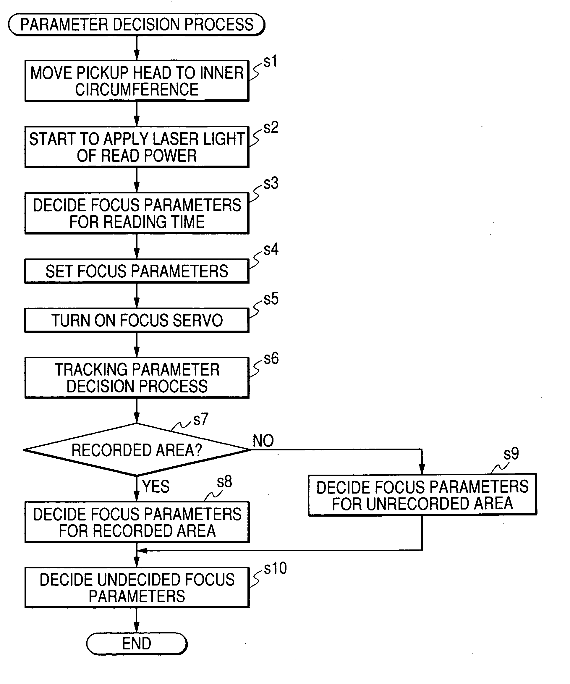
[0057] An optical disk apparatus according to an embodiment of the present invention will be described below.

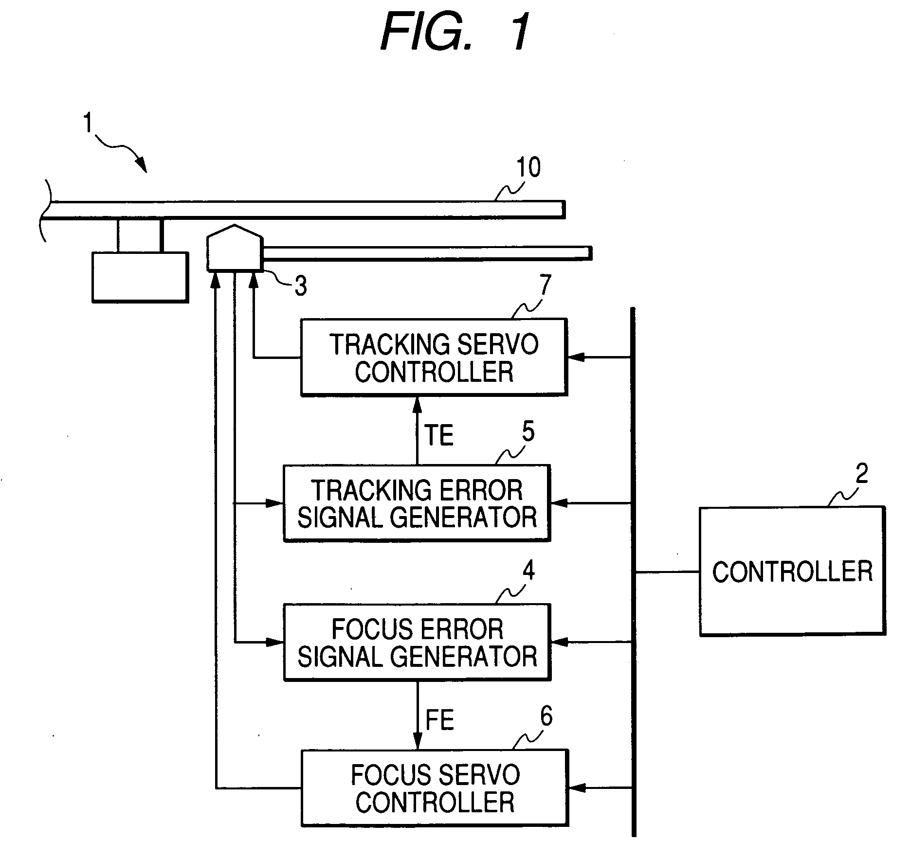
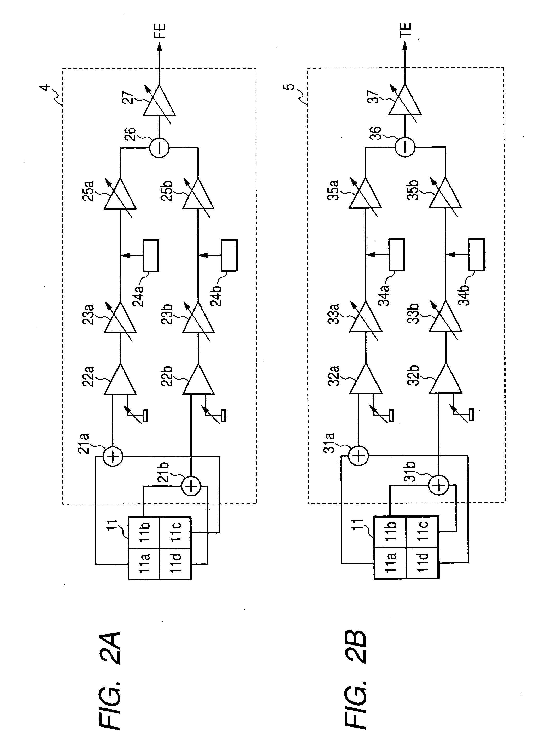
[0058]FIG. 1 is a diagram showing the configuration of a main part of the optical disk apparatus according to the embodiment of the invention. The optical disk apparatus 1 of this embodiment comprises a controller 2 for controlling the operation of a main body, a pickup head 3 for applying a laser light to an optical disk 10 and detecting its reflected light, a focus error signal generator 4 for generating a focus error signal, a tracking error signal generator 5 for generating a tracking error signal, a focus controller 6 for making the focus servo control based on the focus error signal generated by the focus error signal generator 4, and a tracking controller 7 for making the tracking servo control based on the tracking error signal generated by the tracking error signal generator 5. The optical disk apparatus 1 of this embodiment reads data recorded in the optical disk s...


PUM


Abstract

An optical disk apparatus decides a reading time parameters to be set in a tracking error signal generation part at the reading time by applying a laser light of record power to an optical disk. A state where the laser light of record power is applied to the optical disk is artificially produced based on the reading time parameters decided herein. In the state, the recording time parameters to be set in the tracking error signal generation part at the recording time are decided.

Description

BACKGROUND OF THE INVENTION [0001] 1. Field of the Invention [0002] The present invention relates to an optical disk apparatus that reads data from an optical disk such as DVD or CD, and records data in the optical disk. [0003] 2. Description of the Related Art [0004] The optical disk apparatus that can make the readout of data recorded in the optical disks such as DVD and CD and the recording of data has been generally widespread. [0005] The optical disk apparatus applies the laser light of read power to the optical disk set on the main body, and reads the data recorded in this optical disk, as well known. [0006] Also, it applies the laser light of record power that is greater than the read power, and records data in the optical disk. Further, the optical disk apparatus performs a tracking servo control for aligning the position where the laser light is applied to the center of the track of the optical disk of the position at the time of readout and recording and a focus servo cont...

Claims


Application Information

Patent Timeline
IPC IPC(8): G11B7/00
CPCG11B7/0945G11B7/126
Inventor TAKABA, SADAYUKI
Owner FUNAI ELECTRIC CO LTD
Why Eureka
Try Eureka