
Concentrate recycle loop with filtration module

Inactive Publication Date: 2006-05-04
ECOLOCHEM
View PDF22 Cites 44 Cited by
  • Summary
  • Abstract
  • Description
  • Claims
  • Application Information

AI Technical Summary

Benefits of technology

[0017] It is therefore an object of the present invention to provide water purification systems that can operate for a long time before the compartment separation membranes of an electrodeionization unit must be cleaned to remove accumulated biological foulants, and that are environmentally friendly in having a large ratio of the flow rate of the EDI product stream to the flow rate of the supply stream.

Problems solved by technology

For example, highly purified water must be used in the manufacture of electronic microchips: mineral contaminants can induce defects.
However, the need to periodically regenerate ion exchange resins requires a complex arrangement of pumps, piping, valves, and controls with associated large capital and maintenance costs and the use of regenerating chemicals which must be disposed of as chemical waste.
Such cleaning can require the water purification system to be shut down for hours or days.
In addition to the cost associated with the cleaning operation, the shutdown time can, for example, lead to interruption of a production process dependent on purified water, require investment in large storage capacity for purified water, or require investment in an auxiliary water purification system.
Cleanings degrade the compartment separation membranes and can result in the need to frequently replace the expensive membranes.
Deposition of other impurities, such as biological foulants, can foul compartment separation membranes.
Eventually, a large concentration of ions in the concentrating compartments can result in a large conductance across the concentrating compartments.
When the concentration of accumulated polyvalent ions becomes sufficiently large, the polyvalent ions with associated counterions can precipitate as scale on the side of a compartment separation membrane adjacent to a concentrating compartment and thereby foul the membrane.
Nevertheless, although the make up stream may contain no or only a small amount of bacteria and other organisms, it is difficult to maintain complete sterility, and the system illustrated in FIG. 3 of U.S. Pat. No. 6,056,878 does not have a way to eliminate organisms which grow in the concentrate loop.
Filtration of the water used in the make up stream also represents an additional capital cost.
An antiscalant agent injection device contributes to capital and maintenance costs and increases the bulk and weight of a water purification system.
An antibiological agent capable of killing bacteria and other organisms can be injected into the concentrating feed stream, but the antibiological agent must eventually be disposed of as waste, and an antibiological agent injection device contributes to capital and maintenance costs.
Certain antibiological agents can also shorten the life of components in the water purification system.
An ultraviolet light device can irradiate fluid in the concentrate loop to kill bacteria and other organisms; however, neither an ultraviolet light device nor an antibiological agent can eliminate the residue of the killed organisms.
However, a traditional one pass system that provides a portion of the supply stream to the diluting compartments and the remainder to the concentrating compartments of an electrodeionization unit is consumptive of water and has a low ratio of the EDI product stream flow rate to the supply stream flow rate.
The large rate of consumption of water contributes to the operating cost of a traditional one pass system.
The need to inject salt results in increased capital and maintenance costs associated with a salt injection device.
The greater flow rate of supply stream water for a given flow rate of the EDI product stream in a traditional one pass system than in a system incorporating a concentrate loop can result in a traditional one pass water purification system being less environmentally friendly than a water purification system incorporating a concentrate loop.
Thus the system illustrated in FIG. 1 of U.S. Patent Publication No. 2002 / 0125137 A1 does not appear to use the water of the supply stream efficiently.

Method used


Image

  • Concentrate recycle loop with filtration module
  • Concentrate recycle loop with filtration module
  • Concentrate recycle loop with filtration module

Examples


Embodiment Construction

[0027] Embodiments of the invention are discussed in detail below. In describing embodiments, specific terminology is employed for the sake of clarity. However, the invention is not intended to be limited to the specific terminology so selected. A person skilled in the relevant art will recognize that other equivalent components can be employed and other methods developed without parting from the spirit and scope of the invention. All references cited herein are incorporated by reference as if each had been individually incorporated.

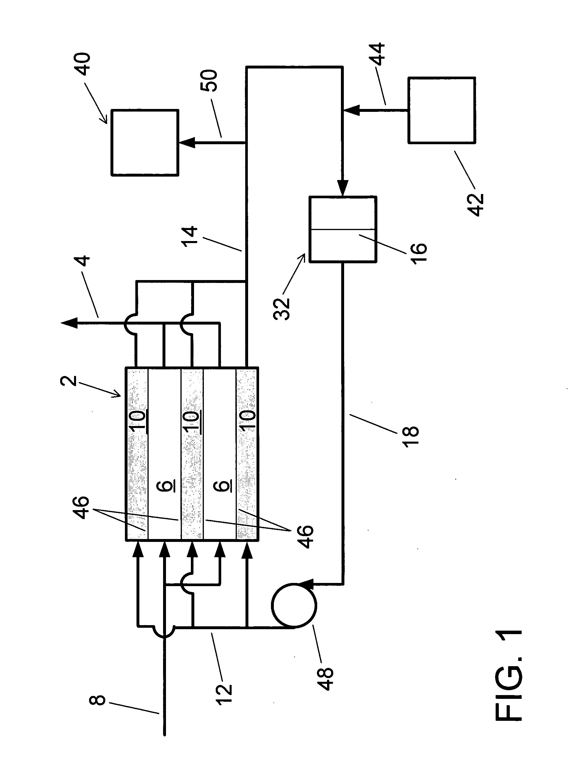
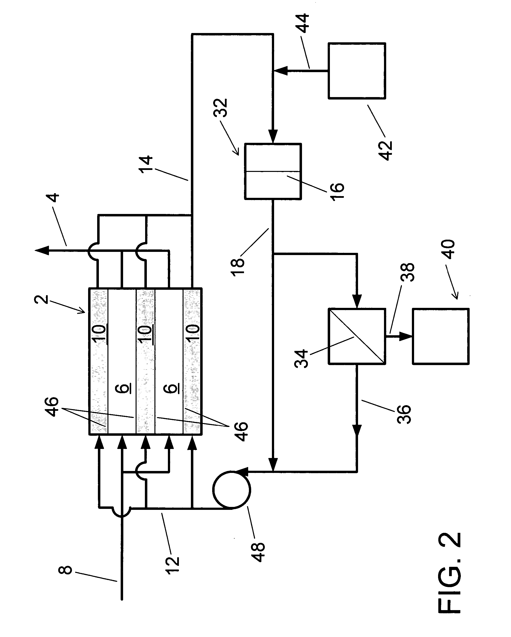
[0028] In an embodiment of a water purification system according to the present invention, shown in FIG. 1, an electrodeionization unit 2 for producing an EDI product stream 4 of purified water is shown. A diluting compartment 6 can receive a diluting feed stream 8. A concentrating compartment 10 can receive a concentrating feed stream 12 and can output a concentrate effluent stream 14. A concentrate filtration membrane 16 can remove biological foulants...


PUM

PropertyMeasurementUnit
Fractionaaaaaaaaaa
Fractionaaaaaaaaaa
Massaaaaaaaaaa

Abstract

Water purification systems include a concentrate filtration membrane and an electrodeionization unit. A concentrate effluent stream from the electrodeionization unit is filtered in the concentrate filtration membrane; the filtered concentrate effluent stream is provided to concentrating compartments of the electrodeionization unit.

Description

BACKGROUND OF THE INVENTION [0001] 1. Field of the Invention [0002] The present invention relates to a water purification system. More particularly, a water purification system in which a concentrate effluent stream is filtered to remove impurities such as biological foulants to produce a filtered concentrate effluent stream which is used in the concentrating compartment of an electrodeionization unit is presented. [0003] 2. Description of the Related Art [0004] Highly purified water having a small concentration of ions and other contaminants is required for a number of industrial applications. For example, highly purified water must be used in the manufacture of electronic microchips: mineral contaminants can induce defects. Highly purified water is used in the power generation industry to minimize the formation of scale on the interior of pipes and thereby ensure good heat transfer within and unrestricted water flow through heat exchange systems. The use of highly purified water r...

Claims


Application Information

Patent Timeline
IPC IPC(8): B01D61/44
CPCB01D61/025B01D61/027B01D61/145B01D61/147B01D61/48B01D61/52B01D61/58C02F1/20C02F1/32C02F1/42C02F1/44C02F1/441C02F1/444C02F1/4695C02F1/50C02F5/00C02F2201/4611C02F2201/46115C02F2201/46145C02F2201/46185C02F2301/043
Inventor HAAS, WILLIAM E.QUEEN, ABEL P.
Owner ECOLOCHEM
Learn More