
Angular ball bearing and rolling bearing

a technology of rolling bearings and bearings, which is applied in the direction of bearing cooling, thickeners, mechanical instruments, etc., can solve the problems of poor rotation accuracy, deterioration of bearing performance, and affecting the rotation accuracy of the bearing

Inactive Publication Date: 2006-04-27
UEDA KEIICHI
View PDF3 Cites 15 Cited by
  • Summary
  • Abstract
  • Description
  • Claims
  • Application Information

AI Technical Summary

Benefits of technology

[0027] The inner ring and outer ring, or the rolling elements are subjected to carbonitriding, and a grease using a urea compound as a thickening agent is sealed in the bearing. As a result, a thin oxide film of a urea compound is formed, and an oil film having a sufficient thickness is formed on the oxide film. Since this thin oxide film of a urea compound is high in adhesion to the carbonitrided layer, even if micro rolling occurs frequently, grease is retained on the rolling surfaces, so that it is possible to effectively prevent lowering of durability by suppressing fretting damage on the raceway surfaces. Also, even if oil film of the grease between the rolling elements and the raceway surfaces breaks, so that the rolling elements and raceway surfaces contact directly, due to the function of the carbonitrided layer provided on the rolling elements or raceway surfaces, development and progression of fretting damage is suppressed for a while. Also, since oil film of the grease is high in adhesion to the carbonitrided layer, even if breakage occurs, it is repaired quickly. Thus, even if the oil film breaks and the rolling elements and raceway surfaces directly contact, it is possible to repair the oil film before fretting damage develops. Thus, resistance to fretting damage markedly improves.

Problems solved by technology

With increase in such vibrating loads, fretting wear damage may develop on the rolling surfaces of such a support bearing.
Such fretting wear damage develops due to minute sliding, minute rolling, minute vibration, etc and has a large influence on deterioration of the bearing performance such as poor rotation accuracy (tone).

Method used


Image

  • Angular ball bearing and rolling bearing
  • Angular ball bearing and rolling bearing
  • Angular ball bearing and rolling bearing

Examples


example 1

Micro Pivoting Wear Test

[0093] The outer ring 90a and inner ring 90b that have been subjected to the abovesaid carbonitriding, and rolling elements 90C (made of SUJ2) were assembled to manufacture a bearing 91 (inner ring inner diameter×outer ring outer diameter×width=20 mm×40 mm×14 mm). At this time, 1 g of urea grease described in Table 1 was sealed (grease is not shown in FIG. 13). Using this bearing 91, Fafnir fretting corrosion test was conducted under ASTM D 4170. Specifically, as shown in FIG. 14, the outer ring 90a and the inner ring 90b were fixed to two bearing retaining portions 96, and a shaft 93 was passed to a bolt 92 in the order shown. And by adjusting the tightening of the bolt 92, a load was applied by a spring 94 (load=2.45 kN). With a chuck portion set in a tester, a pivoting portion 95 and a motor were coupled together by a crank rod, and the motor was rotated in the atmosphere at room temperature. With the pivoting angle set to 12 deg (critical pivoting angle:...

example 2

Microscopic Slide Wear Test

[0098] With rolling elements (made of SUJ2) placed on a plate subjected to the carbonitriding, and using the urea grease described in Table 1 as a grease, micro slide wear tests were conducted by the following method. As for the test conditions at this time, the load applied to the rolling elements was 98 N, amplitude of the rolling elements on the plate was 0.47 mm, the frequency was 30 Hz, the number of loadings was 8.6×10⁵ cycles, and the test time was eight hours.

[0099] And at 5 or more points and in a direction perpendicular to the wear direction, measurement was made on a Talysurf surface profiler and the deepest value was used as the plate wear depth. Also, the wear amount (γ) of the rolling elements was calculated by measuring the wear diameter with a microscope and using the following formula. The results of plate wear depth are shown in FIG. 16, and the results of wear amount of the rolling elements are shown in FIG. 17.

ν=(πh2×(3r−h)) / 3

h=r−(4...

example 3

[0104] An inner ring 81 and an outer ring 83 made of SUJ2 were subjected to the carbonitriding and assembled with rolling elements made of SUJ2 to manufacture the angular ball bearing shown in FIG. 11. And as a grease, urea grease shown in Table 1 was sealed. A load of 6.9 kN (radial load) was applied to the bearing and it was rotated at 2000 rpm. The accumulated breakage probability 10% life at this time was measured. The results are shown in FIG. 18.

[0105] The “Accumulated breakage probability 10% life” refers to the substantially total number of revolutions or operating hours during which 90% (reliability 90%) of identical bearings in a group can be rotated without producing flaking due to rolling fatigue when they are individually rotated under the same conditions.


PUM

PropertyMeasurementUnit
contact angleaaaaaaaaaa
diameteraaaaaaaaaa

Abstract

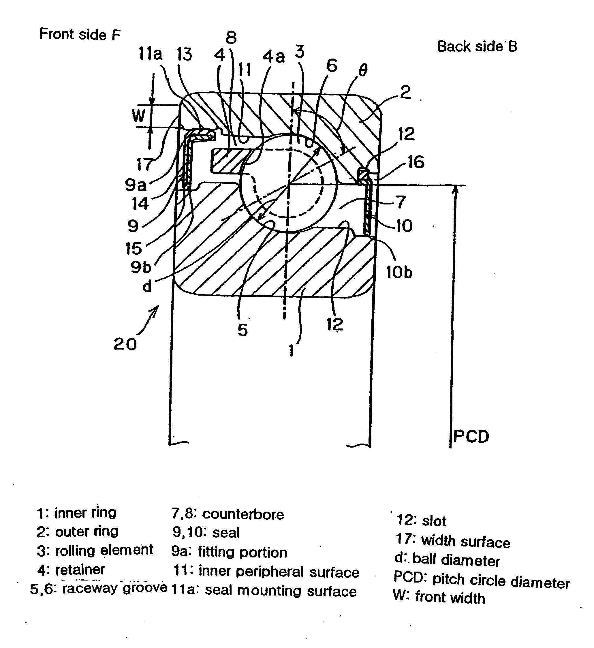
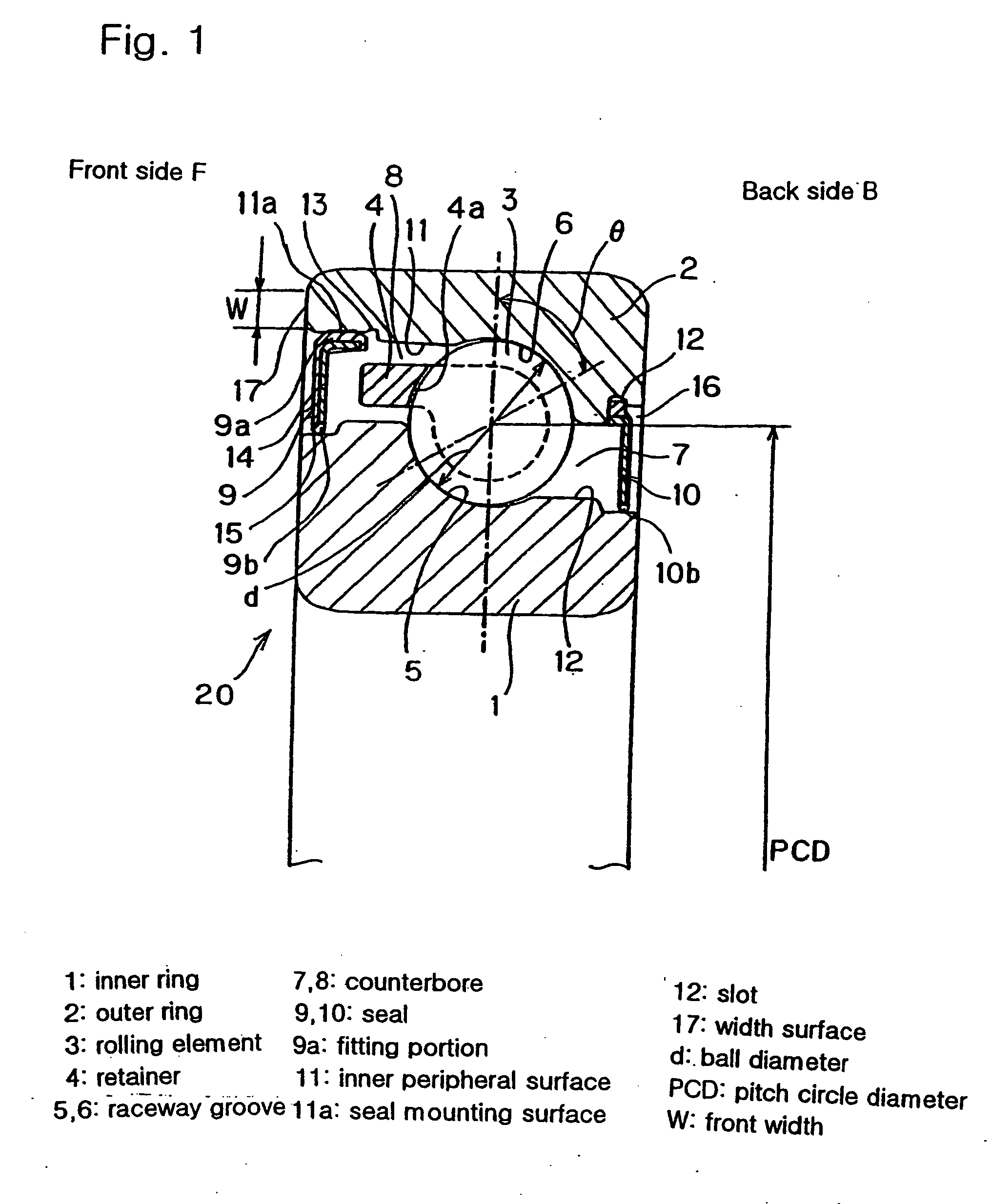
A rolling bearing is proposed in which even though a sealed type, no lowering of strength of the bearing rings or lowering of the front width will not occur for the convenience of mounting of a seal, and design of dimensions equivalent to a non-sealed type bearing and practicability can be achieved, and has fretting resistance. Rolling elements 3 are disposed between an inner ring 1 and an outer ring 2 with seals 9 and 10 provided. The seal 9 arranged on a counterbore 8 of the outer ring 2 is fitted in a pressed state on a peripheral surface portion of a cylindrical surface 11 forming the counterbore 8. By pressing, the seal 9 is mounted without forming a slot. The other seal 10 is fitted in a slot 12. The inner ring and the outer ring, or rolling elements of a bearing comprising the outer ring, inner ring, rolling elements and a retainer are subjected to carbonitriding and a grease using a urea compound as a thickening agent is sealed in the bearing.

Description

TECHNICAL FIELD TO WHICH THE INVENTION BELONGS [0001] This invention relates to angular ball bearings and rolling bearings with a seal used in general purpose industrial machinery at a support portion for a spindle of a machine tool or a ball screw support portion. PRIOR ART [0002] As shown in FIG. 8, an angular ball bearing has a large outer diameter D3 of the inner ring 51 on its loaded (front) side, and a small inner diameter D4 of the outer ring 52 on its loaded (back) side so that a high axial load can be borne. The inner diameter D2 of the inner ring 51 on its non-loaded side, and the inner diameter D5 of the outer ring 52 on its non-loaded side are provided with tapered portions called “counterbores” formed by cutting off one of the shoulders of each raceway groove for assemblability. As a result, the outer diameters D2 and D3 of the inner ring, and the inner diameters D4 and D5 of the outer ring are markedly different from each other. [0003] For such an angular ball bearing,...

Claims


Application Information

Patent Timeline
Patent Type & Authority Applications(United States)
IPC IPC(8): F16C19/00C10M115/08C10M119/24F16C19/16F16C33/62F16C33/64F16C33/66F16C33/78F16C37/00
CPCC10M115/08C10M119/24C10M2215/1026C10M2217/0456F16C19/163F16C33/62F16C33/64F16C33/6633F16C33/7853F16C37/007F16C19/16
Inventor UEDA, KEIICHI
Owner UEDA KEIICHI
Learn More