
Chemical mechanical polish with multi-zone abrasive-containing matrix

a technology of chemical mechanical polish and matrix, which is applied in the direction of grinding/polishing apparatus, grinding machines, manufacturing tools, etc., can solve the problems of non-uniform film thickness across the wafer, the use of multi-zone pressure heads for cmp, and the limited degree of smoothing and local planarization of the technique, etc., to achieve the effect of improving the cmp profil

Inactive Publication Date: 2006-04-13
IBM CORP +1
View PDF14 Cites 27 Cited by
  • Summary
  • Abstract
  • Description
  • Claims
  • Application Information

AI Technical Summary

Benefits of technology

[0017] Advantages of embodiments of the present invention include providing a CMP pad or web having zones with non-uniform fixed abrasive features formed thereon that can produce a mo

Problems solved by technology

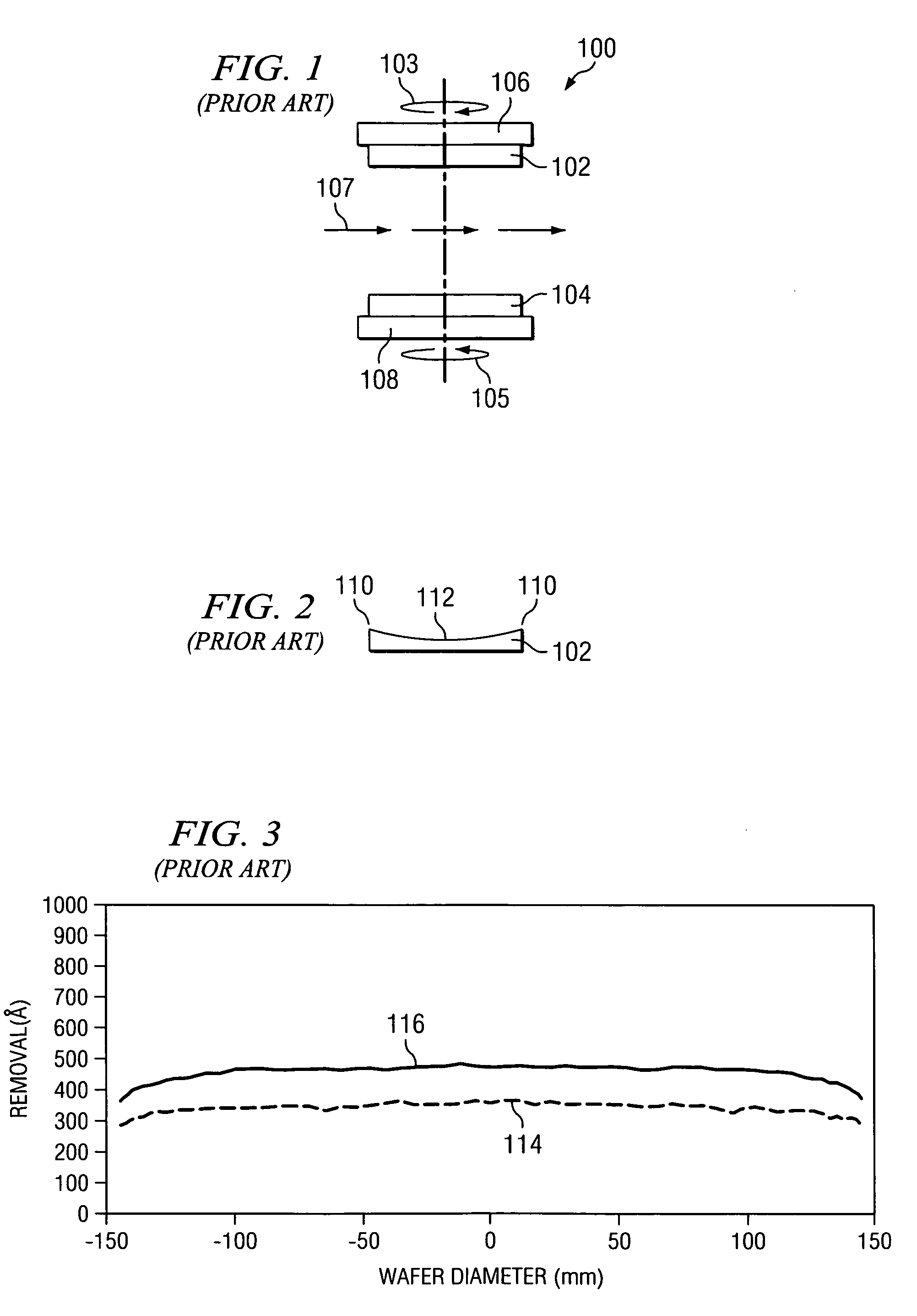
However, these techniques provide only a limited degree of smoothing and local planarization.
One problem with CMP is the non-uniformity of film thickness across a wafer.
However, there are disadvantages of using such a multi-zone pressure head for CMP.
Such a CMP system is complex, and there is a limitation for its use on certain profiles.

Method used


Image

  • Chemical mechanical polish with multi-zone abrasive-containing matrix
  • Chemical mechanical polish with multi-zone abrasive-containing matrix
  • Chemical mechanical polish with multi-zone abrasive-containing matrix

Examples


Embodiment Construction

[0035] The making and using of the presently preferred embodiments are discussed in detail below. It should be appreciated, however, that the present invention provides many applicable inventive concepts that can be embodied in a wide variety of specific contexts. The specific embodiments discussed are merely illustrative of specific ways to make and use the invention, and do not limit the scope of the invention.

[0036] The present invention will be described with respect to preferred embodiments in a specific context, namely, CMP processes for semiconductor wafers. Embodiments of the invention may also be applied, however, to other technologies where polishing processes are used.

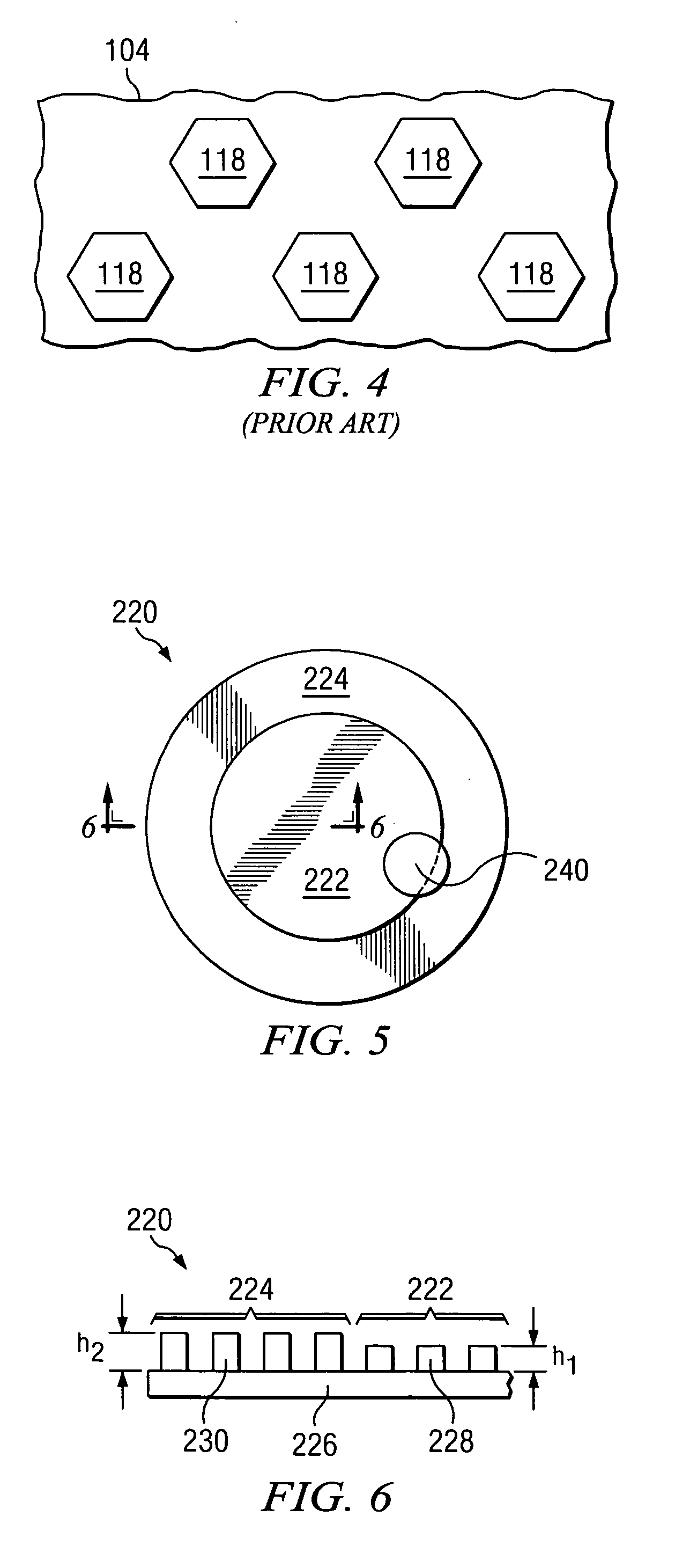
[0037]FIG. 4 shows a prior art CMP device 104 having a uniform matrix of fixed abrasives formed thereon. The CMP device 104 comprises a fixed abrasive (FA) web supplied and commercially available from 3M™ by the product name “3M™ SlurryFree™ CMP Fixed Abrasives”. The CMP device 104 comprises a fixed abrasi...


PUM


Abstract

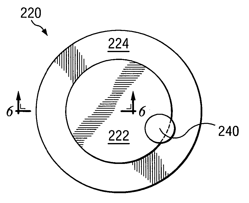
Chemical mechanical polish (CMP) devices, CMP systems, methods of CMP, and methods of manufacturing CMP devices. A CMP device comprises a plurality of zones, with each zone having a matrix of fixed abrasive features disposed therein. The abrasive-containing matrix within each zone has material removal properties that differ from the material removal properties of the abrasive-containing matrixes of the other zones. The material removal property differences of the abrasive-containing matrixes of the zones may achieved by using different abrasive materials, densities, heights, or shapes, or combinations thereof, of the fixed abrasive features within the zones, or by using physical or chemical conditioning. When the novel CMP device is used to planarize a semiconductor wafer, a substantially planar surface with an improved CMP profile results.

Description

TECHNICAL FIELD [0001] The present invention relates generally to manufacturing processes for semiconductor devices, and more particularly to chemical mechanical polish (CMP) processes. BACKGROUND [0002] Semiconductor devices are manufactured by depositing many different types of material layers over a semiconductor workpiece or wafer, and patterning the various material layers using lithography. The material layers typically comprise thin films of conductive, semiconductive and insulating materials that are patterned to form integrated circuits (IC's). In many integrated circuit designs, the various material layers are planarized before depositing subsequent material layers. [0003] There may be a plurality of transistors, memory devices, switches, conductive lines, diodes, capacitors, logic circuits, and other electronic components formed on a single semiconductor die or chip. Semiconductor technology has experienced a trend towards miniaturization, to meet the demands of product s...

Claims


Application Information

Patent Timeline
IPC IPC(8): B24B29/00B24D11/00
CPCB24B37/245B24D7/14
Inventor NAUJOK, MARKUSECONOMIKOS, LAERTIS
Owner IBM CORP
Learn More