Magnetic head for perpendicular magnetic recording and method of manufacturing same

Active Publication Date: 2006-04-13
HEADWAY TECH INC
View PDF6 Cites 20 Cited by
  • Summary
  • Abstract
  • Description
  • Claims
  • Application Information

AI Technical Summary

Benefits of technology

[0018] It is an object of the invention to provide a magnetic head for perpendicular magnetic recording that has a shape capable of preventing problems resulting from the skew and allows a pole layer having a small width to be formed with accuracy, and to provide a method of manufacturing such a magnetic head.

Problems solved by technology

In a magnetic disk drive of the perpendicular magnetic recording system that exhibits a better capability of writing on a recording medium than the longitudinal magnetic recording system, in particular, if the above-mentioned skew is created, problems arise, such as a phenomenon in which data stored on an adjacent track is erased when data is written on a specific track (that is hereinafter called adjacent track erasing) or unwanted writing is performed between adjacent two tracks.
First, when frame plating is employed, it is difficult to form a groove having a small width in the photoresist layer by photolithography.
Therefore, the problem is that it is difficult to reduce the track width when the pole layer is formed by frame plating.
It is thus difficult to reduce the track width by this method, too.
Therefore, it is difficult to form the electrode film for plating without defects at the bottom of the groove when the pole layer is formed in the groove by plating.
If the electrode film is not satisfactorily formed at the bottom of the groove, there may be a case in which the plating film is not fully grown near the bottom of the groove and defects such as keyholes result when the pole layer is formed by plating.
In addition, if the width of the bottom of the groove is reduced, it is difficult to form the pole layer without defects near the bottom of the groove when the pole layer is formed in the groove by sputtering, too.

Method used


Image

  • Magnetic head for perpendicular magnetic recording and method of manufacturing same
  • Magnetic head for perpendicular magnetic recording and method of manufacturing same
  • Magnetic head for perpendicular magnetic recording and method of manufacturing same

Examples


first embodiment

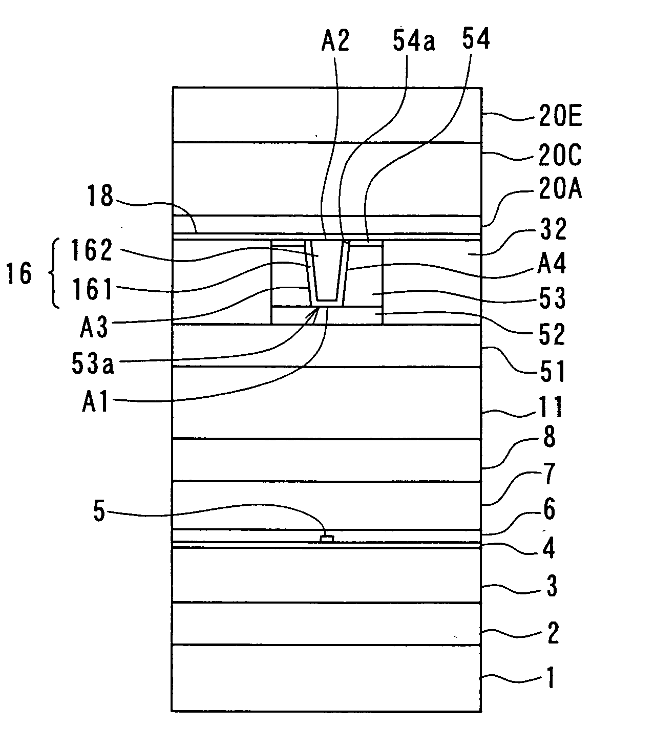
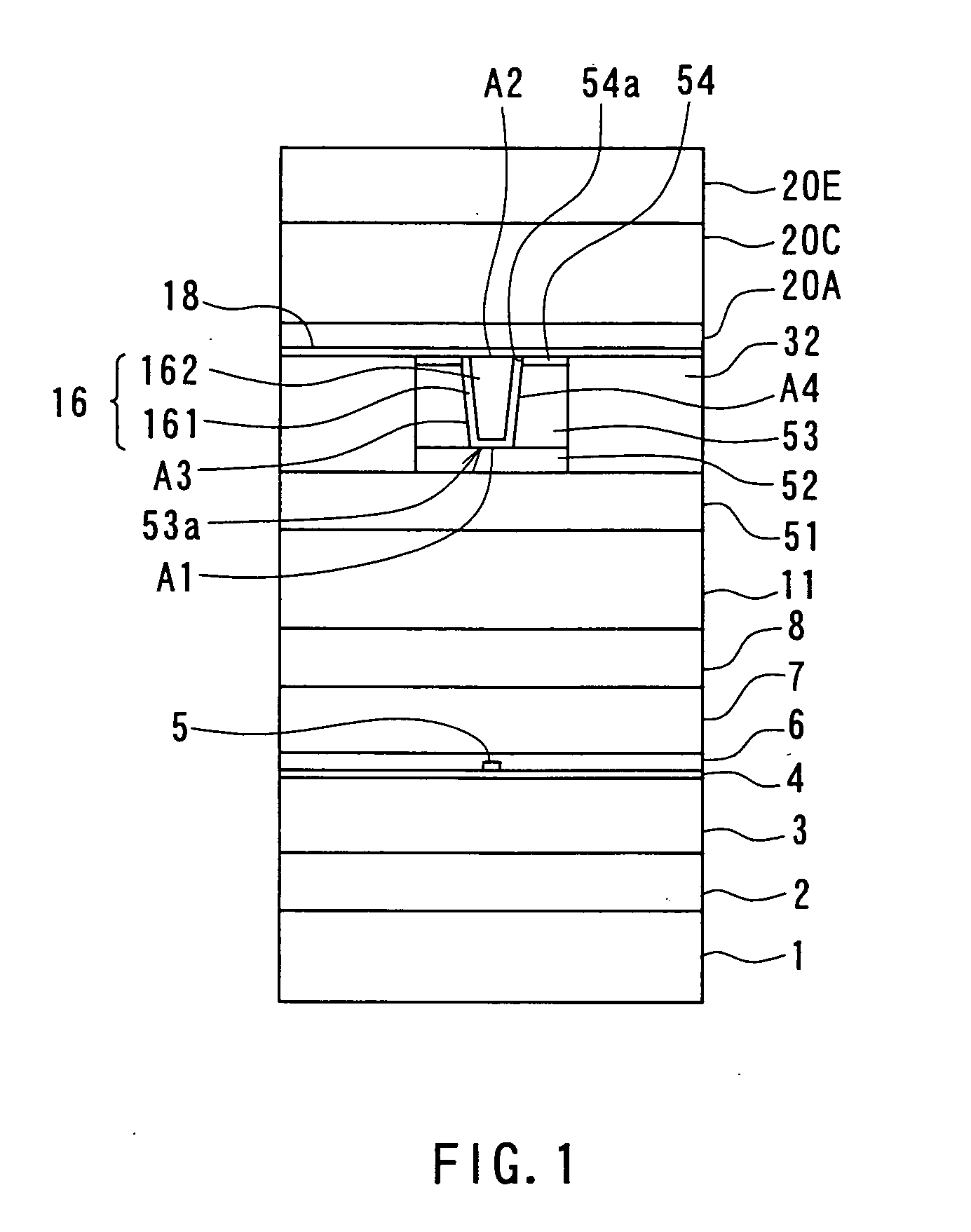
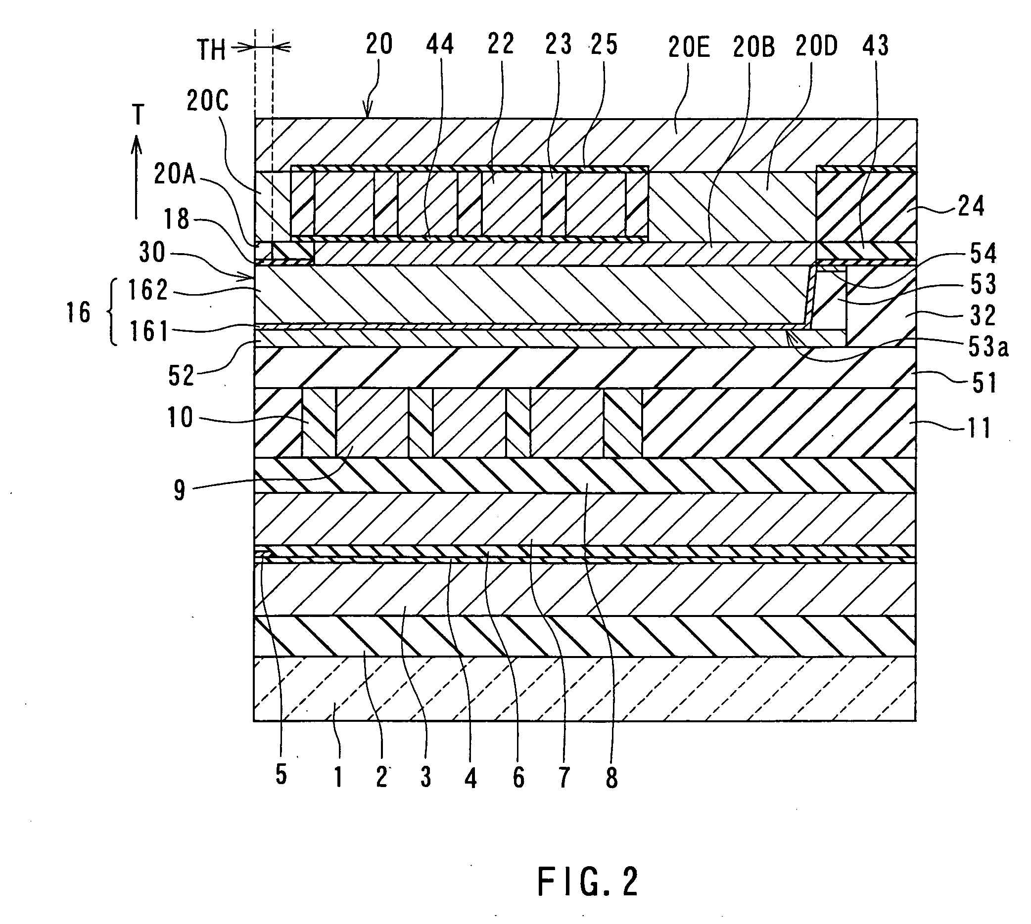
[0092] Preferred embodiments of the invention will now be described in detail with reference to the accompanying drawings. Reference is now made to FIG. 1 and FIG. 2 to describe the configuration of a magnetic head for perpendicular magnetic recording of a first embodiment of the invention. FIG. 1 is a front view for illustrating the medium facing surface of the magnetic head of the embodiment. FIG. 2 is a cross-sectional view for illustrating the configuration of the magnetic head of the embodiment. FIG. 2 illustrates a cross section orthogonal to the medium facing surface and a surface of a substrate. The arrow indicated with T in FIG. 2 shows the direction of travel of a recording medium.

[0093] As shown in FIG. 1 and FIG. 2, the magnetic head for perpendicular magnetic recording (hereinafter simply called the magnetic head) of the embodiment comprises: a substrate 1 made of a ceramic such as aluminum oxide and titanium carbide (Al2O3—TiC); an insulating layer 2 made of an insula...

second embodiment

[0171] A magnetic head and a method of manufacturing the same of a second embodiment of the invention will now be described. Reference is now made to FIG. 16A to FIG. 25A, and FIG. 16B to FIG. 25B to describe the method of manufacturing the magnetic head of the second embodiment. FIG. 16A to FIG. 25A each illustrate a cross section of the layered structure in the course of the manufacturing process of the magnetic head, the cross section being orthogonal to the medium facing surface and the substrate. FIG. 16B to FIG. 25B each illustrate a cross section of a portion of the layered structure near the medium facing surface, the cross section being parallel to the medium facing surface. Portions closer to the substrate 1 than the insulating layer 51 are omitted in FIG. 16A to FIG. 25A and FIG. 16B to FIG. 25B.

[0172] The method of manufacturing the magnetic head of the second embodiment includes the steps up to the step of forming the nonmagnetic layer 53P that are the same as those of...

third embodiment

[0199] A magnetic head and a method of manufacturing the same of a third embodiment of the invention will now be described. Reference is now made to FIG. 27A to FIG. 33A, and FIG. 27B to FIG. 33B to describe the method of manufacturing the magnetic head of the third embodiment. FIG. 27A to FIG. 33A each illustrate a cross section of the layered structure in the course of the manufacturing process of the magnetic head, the cross section being orthogonal to the medium facing surface and the substrate. FIG. 27B to FIG. 33B each illustrate a cross section of a portion of the layered structure near the medium facing surface, the cross section being parallel to the medium facing surface. Portions closer to the substrate 1 than the insulating layer 51 are omitted in FIG. 27A to FIG. 33A and FIG. 27B to FIG. 33B.

[0200] The method of manufacturing the magnetic head of the third embodiment includes the steps up to the step of forming the groove 53a in the nonmagnetic layer 53P that are the s...


PUM

PropertyMeasurementUnit
Thicknessaaaaaaaaaa
Currentaaaaaaaaaa
Electrical conductoraaaaaaaaaa

Abstract

A pole-layer-encasing layer made of a nonmagnetic material is disposed on an underlying layer made of a nonmagnetic conductive material. The encasing layer has a groove that penetrates. A pole layer is disposed in the groove. The pole layer is formed by plating through feeding a current to the underlying layer. A polishing stopper layer made of a nonmagnetic conductive material is disposed on the top surface of the encasing layer. The polishing stopper layer indicates the level at which polishing for controlling the thickness of the pole layer is stopped. The polishing stopper layer has an opening that penetrates, and the edge of the opening is located directly above the edge of the groove located in the top surface of the encasing layer.

Description

BACKGROUND OF THE INVENTION [0001] 1. Field of the Invention [0002] The present invention relates to a magnetic head for perpendicular magnetic recording that is used for writing data on a recording medium by using a perpendicular magnetic recording system and to a method of manufacturing such a magnetic head. [0003] 2. Description of the Related Art [0004] The recording systems of magnetic read / write devices include a longitudinal magnetic recording system wherein signals are magnetized in the direction along the surface of the recording medium (the longitudinal direction) and a perpendicular magnetic recording system wherein signals are magnetized in the direction perpendicular to the surface of the recording medium. It is known that the perpendicular magnetic recording system is harder to be affected by thermal fluctuation of the recording medium and capable of implementing higher linear recording density, compared with the longitudinal magnetic recording system. [0005] Like magn...

Claims


Application Information

Patent Timeline
IPC IPC(8): G11B5/147
CPCG11B5/1278G11B5/3116G11B5/314G11B5/3163Y10T29/49021Y10T29/49046Y10T29/49052Y10T29/49041Y10T29/49048Y10T29/49043Y10T29/49044Y10T29/4906
Inventor SASAKI, YOSHITAKAARAKI, HIRONORIITOH, HIROYUKIISHIZAKI, KAZUO
Owner HEADWAY TECH INC
Why Eureka
Try Eureka