Bayonet spacer retention system for variable turbine geometry vane packs

Inactive Publication Date: 2015-05-07
BORG WARNER INC
View PDF3 Cites 3 Cited by
  • Summary
  • Abstract
  • Description
  • Claims
  • Application Information

AI Technical Summary

Benefits of technology

This patent describes a way to connect two parts called vane rings using multiple spacer connectors. Each spacer connector has a body and two shaft portions that stick out from opposite ends of the body. These shaft portions have bumps on their outer surface. The shaft portions fit into matching holes in the vane ring, and the bumps prevent the shaft portions from moving back through the holes. This design helps control the space between the parts without needing close tolerances, press fits, expensive welds, or other complicated processes.

Problems solved by technology

Unfortunately, the increase in efficiency due the side clearances is inversely proportional to the propensity of the vane pack (26) to wear, stick, or completely jam due to thermal deformation in the turbine housing (14) being transferred to the vane pack (26).
However, such studs are difficult to secure so that they do not unscrew when subjected to vibration, especially in situations where there are high temperature (from 740° C. to 1050° C.).
hus, what may appear to be a simple clamping device (i.e., a nut and bolt) is actually a complicated engineering issue, which typically requires the use of exotic and expensive materials for the components so that the clamp load is maintained over the aforementioned range of temperatures.
However, during turbocharger operation, such a vane pack has experienced problems in that the spacers become separated from the vane rings.

Method used


Image

  • Bayonet spacer retention system for variable turbine geometry vane packs
  • Bayonet spacer retention system for variable turbine geometry vane packs
  • Bayonet spacer retention system for variable turbine geometry vane packs

Examples


Embodiment Construction

[0021]Arrangements described herein relate to a retention system and method for a vane ring assembly. Detailed embodiments are disclosed herein; however, it is to be understood that the disclosed embodiments are intended only as exemplary. Therefore, specific structural and functional details disclosed herein are not to be interpreted as limiting, but merely as a basis for the claims and as a representative basis for teaching one skilled in the art to variously employ the aspects herein in virtually any appropriately detailed structure. Further, the terms and phrases used herein are not intended to be limiting but rather to provide an understandable description of possible implementations. Arrangements are shown in FIGS. 3-9, but the embodiments are not limited to the illustrated structure or application.

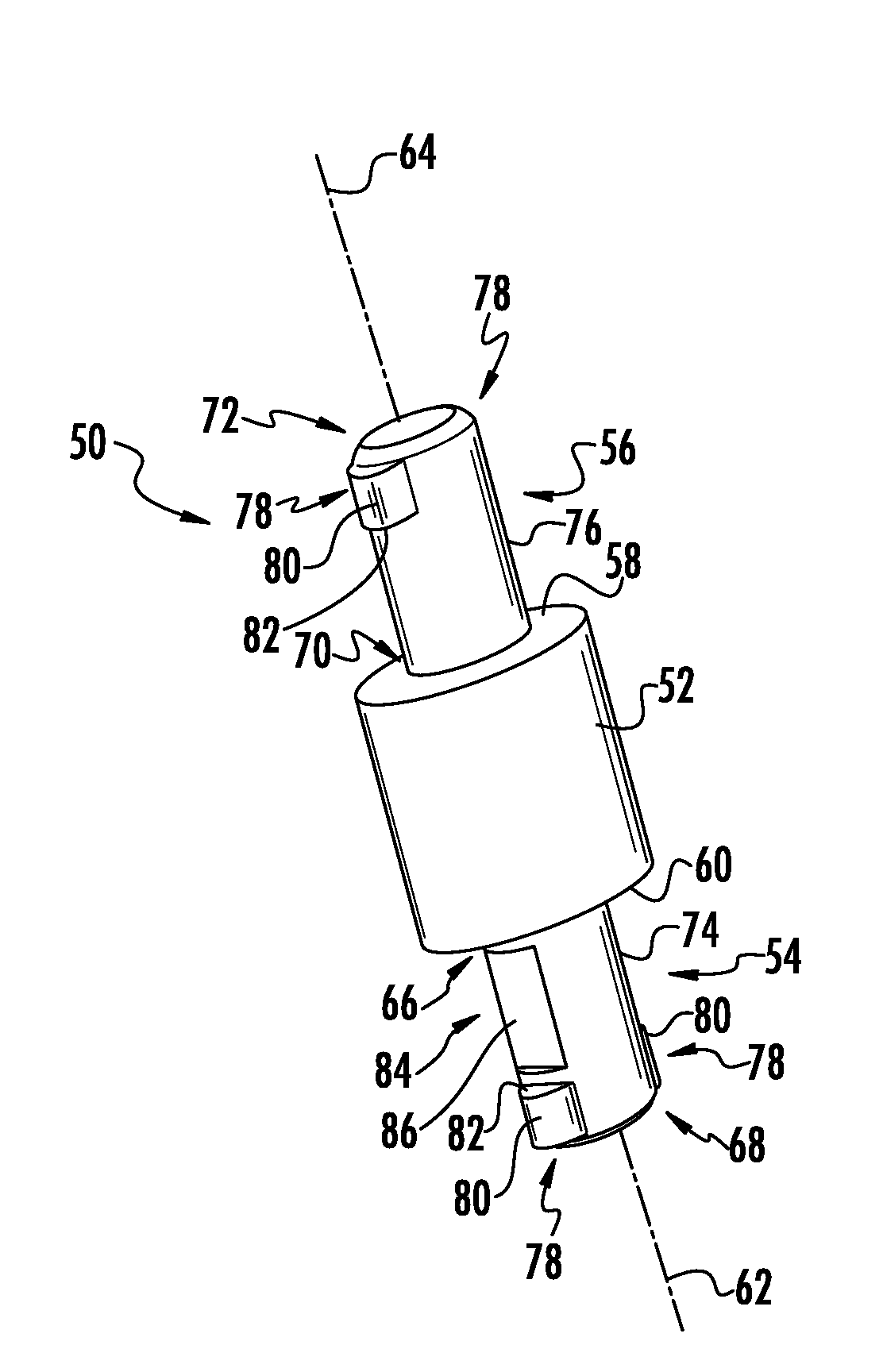
[0022]A vane pack according to embodiments herein can include a plurality of spacer connectors. The spacer connectors can have any suitable configuration. An example of one possible...


PUM

PropertyMeasurementUnit
Angleaaaaaaaaaa
Angleaaaaaaaaaa

Abstract

A variable geometry turbocharger includes a vane pack having rotatable vanes constrained by a pair of vane rings connected by a plurality of spacer connectors. The spacer connectors can include a spacer body for maintaining a minimum spacing between the vane rings. The spacer connectors are configured for bayonet mounting to at least one of the vane rings. To that end, the spacer connectors can include shaft portions extending from opposing sides of the spacer body. A plurality of transverse protrusions can extend outwardly from each shaft portion. Each shaft portion can be received in a respective in a vane ring. The spacer connectors can be rotated such that the transverse protrusions are offset from aperture portions that allow passage of the transverse portions, thereby retaining the vane rings in place in spaced relation. Such a system avoids close tolerances, press fits, expensive bolted joints or weld processes.

Description

FIELD OF THE INVENTION[0001]Embodiments related in general to turbochargers and, more particularly, to vane packs for variable turbine geometry turbochargers.BACKGROUND OF THE INVENTION[0002]Turbochargers are a type of forced induction system. They deliver air, at greater density than would be possible in the normally aspirated configuration, to the engine intake, allowing more fuel to be combusted, thus boosting the engine's horsepower without significantly increasing engine weight. A smaller turbocharged engine, replacing a normally aspirated engine of a larger physical size, will reduce the mass and can reduce the aerodynamic frontal area of the vehicle.[0003]FIG. 1 shows a typical variable geometry turbocharger (10). Generally, turbochargers (10) use the exhaust flow from the engine exhaust manifold to drive a turbine wheel (12), which is located in a turbine housing (14) to form a turbine stage (16). The energy extracted by turbine wheel (12) is translated to a rotating motion ...

Claims


Application Information

Patent Timeline
IPC IPC(8): F01D17/16F02B37/24
CPCF02B37/24F01D17/165F02B39/00F05D2220/40Y02T10/12Y10T29/49323F02B37/14F02B37/18F02D23/00F05D2260/33
Inventor HEDDY, III, GEORGE E.
Owner BORG WARNER INC
Why Eureka
Try Eureka