
Mig welding machine having 115v inverter

a welding machine and inverter technology, applied in the field of welding systems, can solve the problems of detracting from affecting the welding efficiency of the welder, and the portability of the welder is relatively poor, so as to improve the power factor characteristics and improve portability

Active Publication Date: 2006-04-13
ILLINOIS TOOL WORKS INC
View PDF20 Cites 18 Cited by
  • Summary
  • Abstract
  • Description
  • Claims
  • Application Information

AI Technical Summary

Benefits of technology

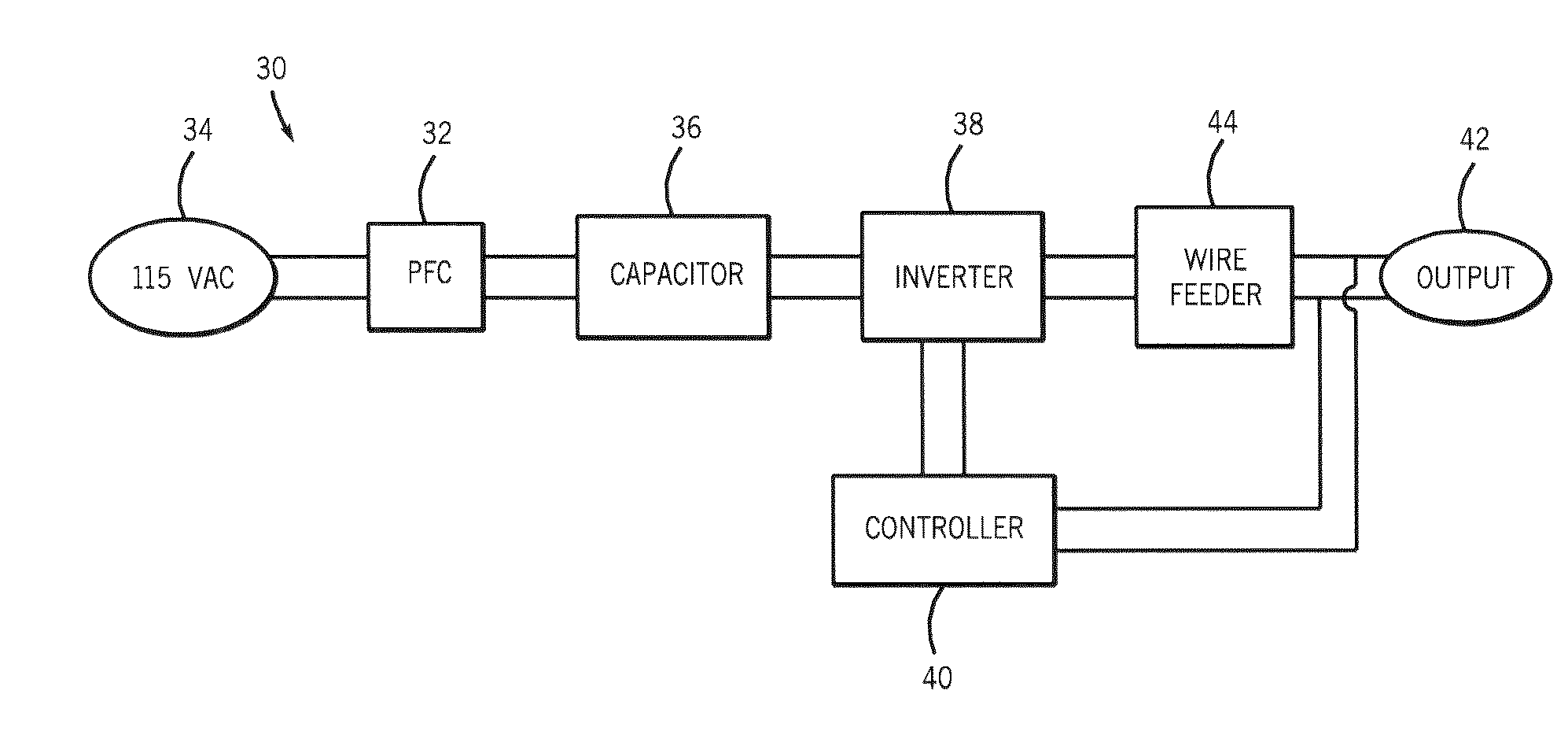
The 115 volt inverter-based MIG welding machine is more portable, efficient, and capable of delivering higher output ratings with improved power factor, reducing weight by half and increasing usable output power from 60-65% to 80-85% while minimizing line draw.

Problems solved by technology

Generally, however, the output welding current of these portable machines must be limited so that line current does not exceed the capacity of the circuit breaker protecting the 115VAC line.
These features detract from the portability of the welder.
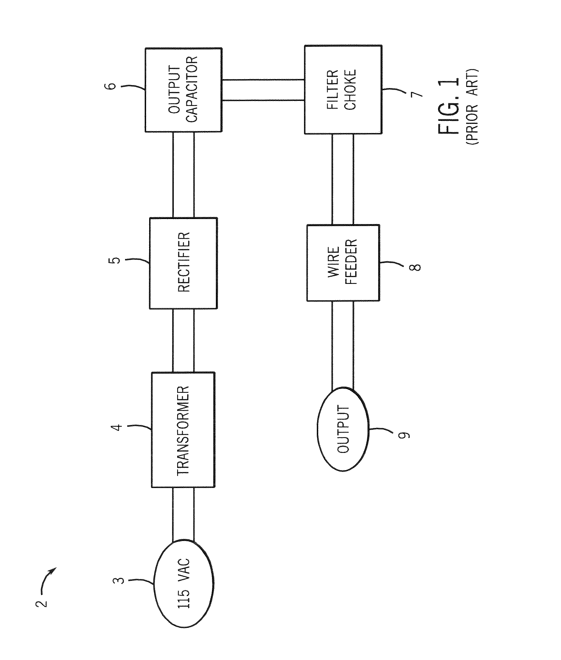
As a result, the welder has a relatively poor power factor.
In addition the overall power efficiency of the transformer rectifier circuit is fairly low.

Method used


Image

  • Mig welding machine having 115v inverter
  • Mig welding machine having 115v inverter
  • Mig welding machine having 115v inverter

Examples


Embodiment Construction

[0026] Referring to FIG. 2, a welding-type system 10 is show incorporating the present invention. System 10 includes a portable power source 12, which can be an AC or a DC welding power supply operable in either a constant current (CC) or constant voltage (CV) mode. The power source 12 has a work cable 14 and clamp 16 designed to hold a workpiece 18 for welding. Power source 12 is also connected to a wire feeder 20 via an input power cord or cable 21. Cable 21 is designed to translate power from the power source 12 or other power supply to the wire feeder. Also connected between the power source 12 and the wire feeder 20 is a weld cable 22. The wire feeder 20 also includes a welding torch or gun 24 and a voltage sensing lead with clip (not shown) configured to provide voltage at the weld feedback to the wire feeder and / or power source. A shielding gas cylinder 28 is also connected to the wire feeder 20 to provide shielding gas through hose 29 for the welding process. Alternately, th...


PUM

PropertyMeasurementUnit
voltageaaaaaaaaaa
power factoraaaaaaaaaa
timeaaaaaaaaaa

Abstract

The present invention is directed to a MIG welding machine having a 115 volt inverter. Incorporation of the 115 volt inverter into the MIG welding power source reduces the weight of the power source thereby increasing its portability. The power source may include a power factor correction circuit to provide a near-unity power factor such that output power of the inverter is more efficiently provided. Additionally, the 115 volt inverter is constructed such that for short periods of time, the inverter may output power at a level that exceeds its power rating.

Description

CROSS-REFERENCE TO RELATED APPLICATION [0001] The present invention is a divisional and claims priority of U.S. patent application Ser. No. 10 / 605,332 filed Sep. 23, 2003, the disclosure of which is incorporated herein.BACKGROUND OF THE INVENTION [0002] The present invention relates generally to welding systems and, more particularly, to a welding machine designed to introduce a consumable wire electrode to a weld and having an inverter to condition a 115 volt raw power input to a form usable by the welding process. [0003] MIG welding, formerly known as Gas Metal Arc Welding (GMAW), combines the techniques and advantages of TIG welding's inert gas shielding with a continuous, consumable wire electrode. An electrical arc is created between the continuous, consumable wire electrode and a workpiece. As such, the consumable wire functions as the electrode in the weld circuit as well as the source of filler metal. MIG welding is a relatively simple process that allows an operator to conc...

Claims


Application Information

Patent Timeline
Patent Type & Authority Applications(United States)
IPC IPC(8): B23K9/10
CPCB23K9/1006B23K9/1043
Inventor MATUS, TIM A.VOGEL, BERNARD J.ALBRECHT, BRUCE
Owner ILLINOIS TOOL WORKS INC
Learn More