
Transmission with internal protective shield and bicycle incorporating same

Inactive Publication Date: 2006-04-06
HONDA MOTOR CO LTD
View PDF7 Cites 10 Cited by
  • Summary
  • Abstract
  • Description
  • Claims
  • Application Information

AI Technical Summary

Benefits of technology

[0007] One objective of the invention is to provide a transmission for a bicycle in which the entry of foreign objects, such as abrasion powder, into the guide surfaces of the sliding mechanism, which enables the first sprocket to move in the axial direction, is inhibited or prevented. The invention thus enables a first sprocket to move in the axial direction more smoothly and to stretch the time between maintenance. Another objective of the invention is to facilitate the attachment of a cover to the outer member. Another objective of the invention is to further reduce the size of the transmission.
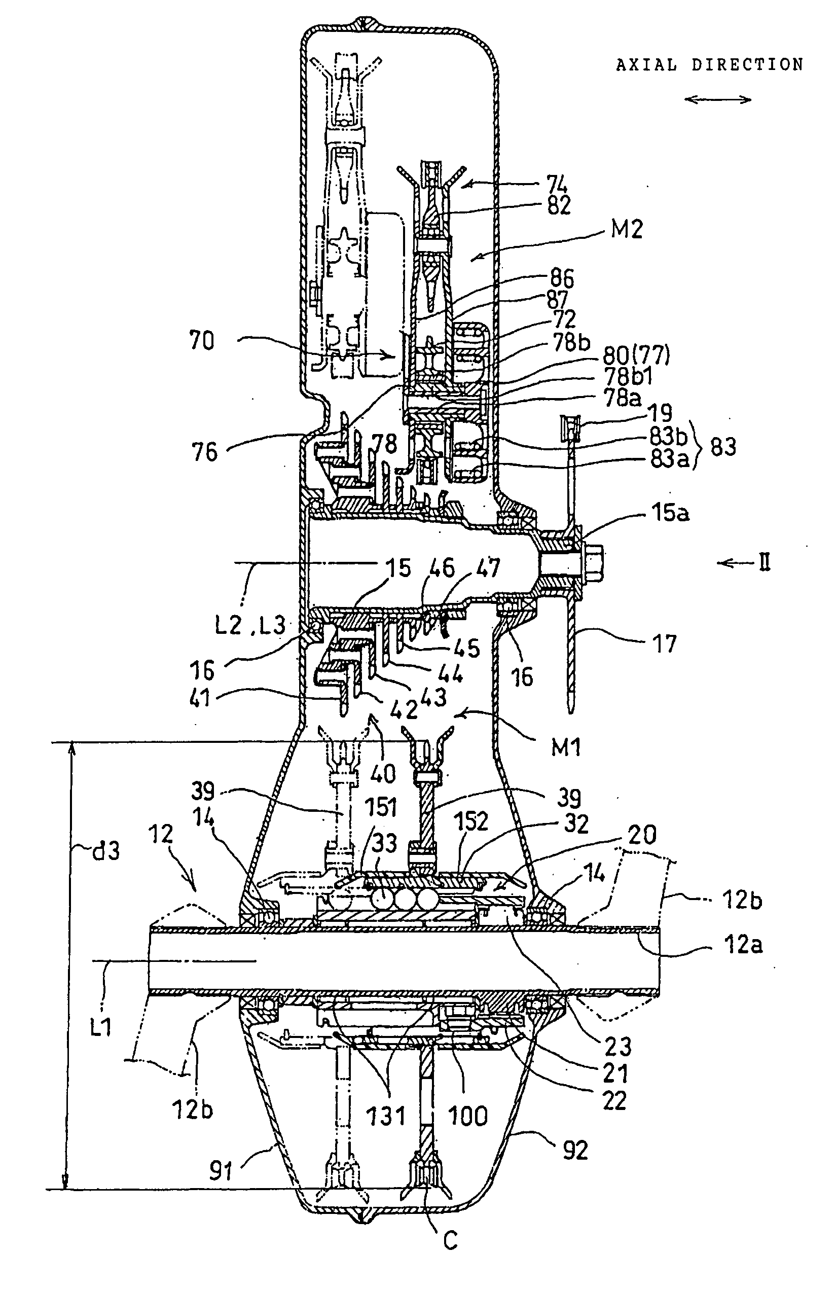
[0010] According to this invention, the guide surfaces of the sliding mechanism are covered with the dust cover regardless of the position of the first sprocket that moves in the axial direction. Thus, foreign objects including abrasion powder generated as a result of the engagement of the chain with the sprockets or the contact thereof with the derailer, cannot easily enter the guide surfaces and hence their attachment to the guide surfaces can be inhibited or prevented. Thus, when the chain moves in the axial direction and causes the first sprocket, moving integrally with the outer member, to move in the axial direction, hindrance of the movement of the first sprocket in the axial direction, caused by the foreign objects attached to the guided surfaces can be inhibited or prevented.
[0012] According to this invention, since the dust cover covers all the side surfaces of the inner member, entry of foreign objects into the guide surfaces can be inhibited or prevented in the entire region of the inner member in a circumferential direction. In addition, since the areas of openings formed in the dust cover are reduced due to the presence of the tapered portions, entry of foreign objects through the openings is inhibited when the dust cover moves in the axial direction integrally with the outer member.
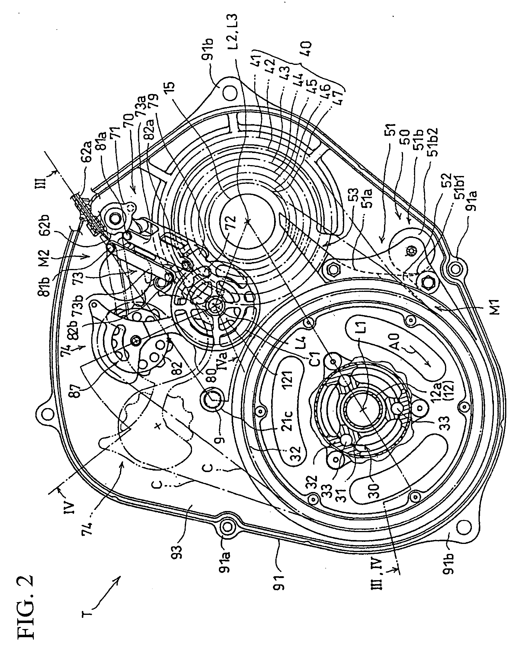
[0016] According to this invention, when the chain is shifted among the transmission sprockets, the dust cover inhibits or prevents the entry of abrasion powder falling down from around the guide pulley. This location is where a relatively great amount of abrasion powder could fall into the guide surfaces of the sliding mechanism as a result of the guide pulley making contact with the chain. According to the invention, even when the guide pulley is located at a position which makes the shortest distance between the guide member and the rotational centerline of the rotation shaft to be smaller than the outer diameter of the first sprocket, and when the first sprocket and the guide pulley are juxtaposed to each other, the entry of abrasion powder into the guide surfaces can be inhibited or prevented with a reliability.
[0017] Accordingly, through use of the present invention it is possible to stretch the time between maintenance of the transmission because the entry of foreign objects into the guide surfaces is prevented or further inhibited. Accordingly, the first sprocket can move in the axial direction more smoothly and the gears in the transmission can be shifted more smoothly. In some embodiments, since the dust cover is attached to the outer member via the concave-convex engagement using engagement portions formed on the dust cover and the outer member, the attachment of the dust cover is facilitated. In addition, since extra attachment members are not required, the cost for the transmission can be reduced. In some embodiments, the first sprocket and the guide pulley can be juxtaposed closely to each other while ensuring smooth movement of the first sprocket in the axial direction. Thus, it is possible to make the transmission compact.

Problems solved by technology

Thus, the drive sprocket cannot move in the axial direction smoothly.
The attachment of abrasion powder to the guide surface of the housing grooves is difficult to identify visually when a transmission mechanism is housed in a case.

Method used


Image

  • Transmission with internal protective shield and bicycle incorporating same
  • Transmission with internal protective shield and bicycle incorporating same
  • Transmission with internal protective shield and bicycle incorporating same

Examples


Embodiment Construction

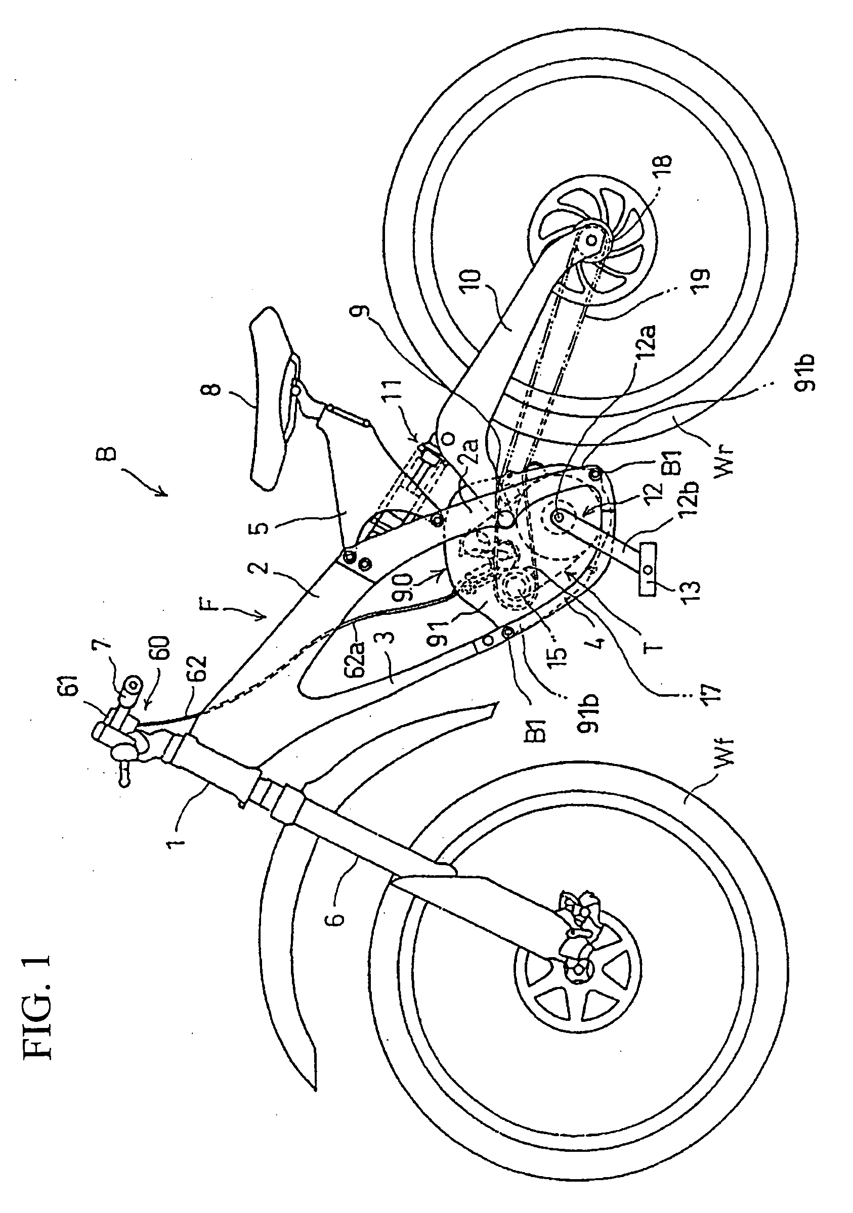
[0027] With reference to FIG. 1, a bicycle B provided with a transmission T to which the present invention is applied includes: a body frame F; a crankshaft 12 mounted with pedals; and a transmission gear including a transmission T, an output shaft 15 which is driven to rotate by power transmitted after a transmission is performed, and a drive-power transmitting mechanism.

[0028] The body frame F includes: a head pipe 1 which rotatably supports the shaft of a front wheel Wf in the lower end of the head pipe 1 and steerably supports a front fork 6 having a handlebar 7 at the top of the head pipe 1; a pair of left and right mainframes 2 which obliquely extend from the head pipe 1 downwards to the rear; down tubes 3 which obliquely extend from the front ends of the respective two mainframes 2 downwards to the rear; a pair of left and right under tubes 4 which connect rear ends of the two main frames 2 to rear ends of the down tubes 3; and a saddle frame 5 which extends from each of the...


PUM


Abstract

A transmission includes a ball spline mechanism having an outer member which can rotate integrally with an inner member by means of balls housed in guide grooves and which can move in the axial direction; and a derailer which shifts a chain wrapped around a first sprocket moving integrally with the outer member from one transmission sprocket to another among a plurality of operating sprockets. The inner member and the outer member include guide surfaces through which the outer member is guided to move in the axial direction through the balls. The outer member is provided with a dust cover for covering the guide surfaces, regardless of the axial position of the first sprocket.

Description

CROSS-REFERENCE TO RELATED APPLICATIONS [0001] The present invention claims priority under 35 USC 119 based on Japanese patent application No. 2004-285494, filed on Sep. 29, 2004. The subject matter of this priority document is incorporated by reference herein. BACKGROUND OF THE INVENTION [0002] 1. Field of the Invention [0003] The present invention relates to a transmission equipped with a sliding mechanism that enables a sprocket, around which a chain is wrapped, to move in an axial direction, relative to a shaft on which the sprocket is mounted. The transmission is provided, for example, for bicycles. More particularly, the invention relates to a transmission mechanism of the type having a protection mechanism against foreign objects. [0004] 2. Background Art [0005] A transmission in which a gear shift is performed by shifting a chain among a plurality of sprockets includes a transmission for bicycles that is disclosed in Japanese Laid-Open Patent document No. 2004-155280. This t...

Claims


Application Information

Patent Timeline
IPC IPC(8): F16H59/00F16H61/00F16H63/00B62M9/131B62M9/04B62M9/134B62M9/138F16D3/84F16H9/06F16H9/24F16H55/30
CPCB62M9/04F16H9/24F16H57/031F16H2057/02086
Inventor KAGA, HIROYUKIKIMURA, TATSURO
Owner HONDA MOTOR CO LTD
Learn More