
Optical add/drop multiplexer with reconfigurable add wavelength selective switch

a technology of optical multiplexers and selective switches, applied in the field of wdm (wavelength division multiplexing) optical systems, can solve the problem of difficult frequency-selective processing of optical signals with passive optical components of reasonable cos

Active Publication Date: 2006-04-06
CISCO TECH INC
View PDF66 Cites 32 Cited by
  • Summary
  • Abstract
  • Description
  • Claims
  • Application Information

AI Technical Summary

Benefits of technology

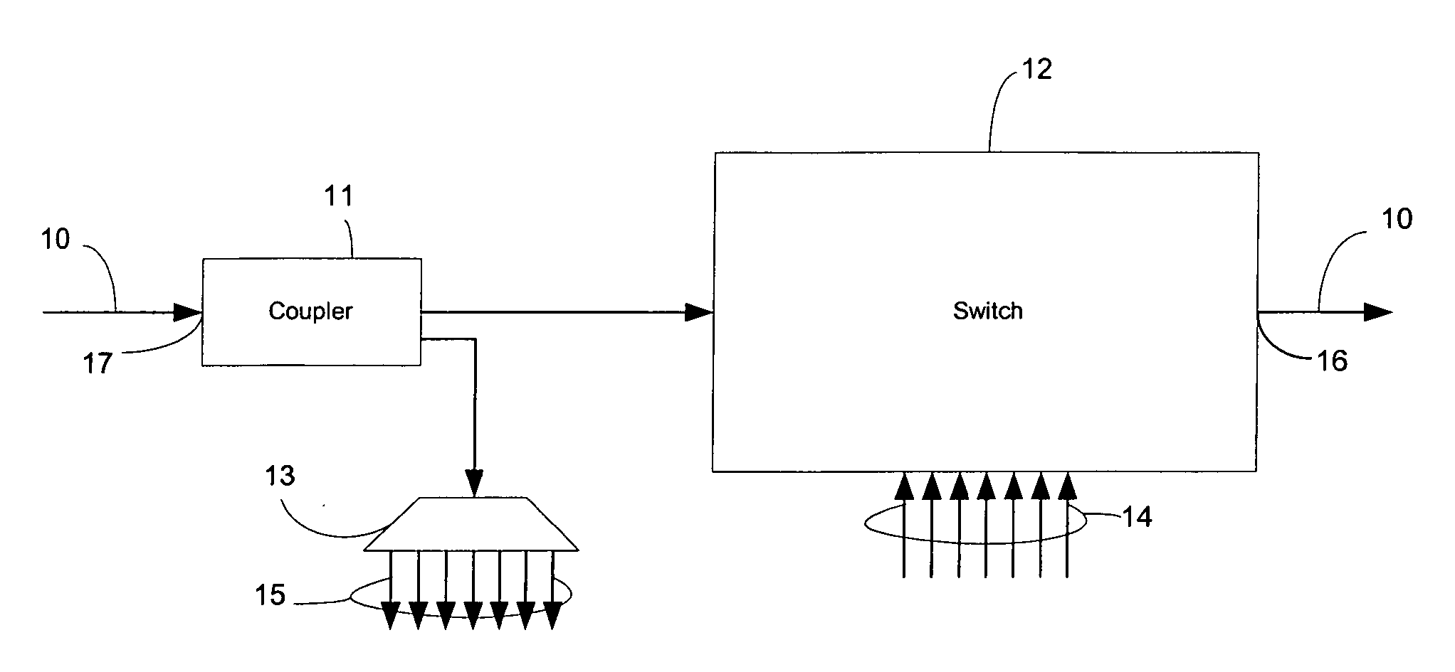
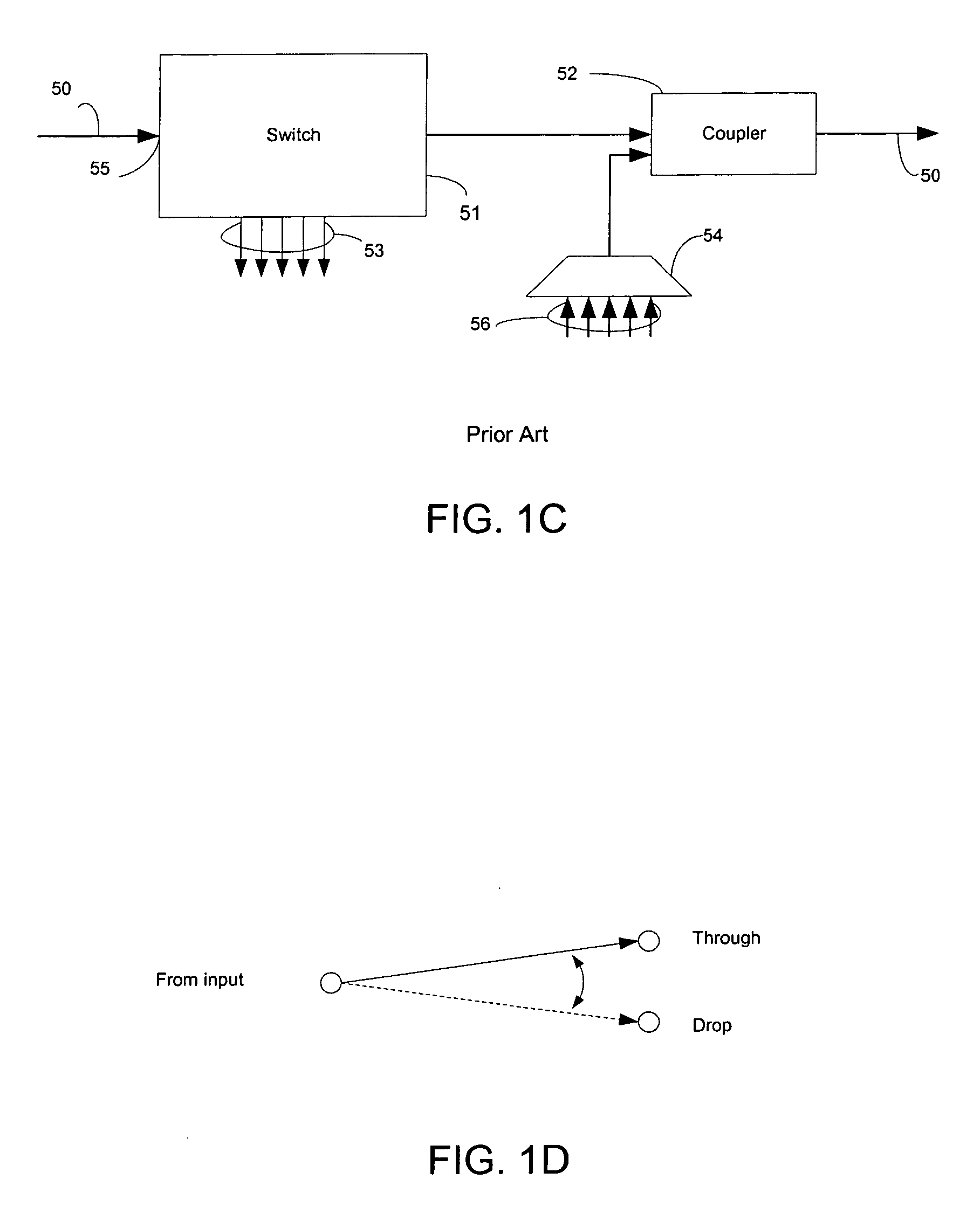
[0030] The resulting add / drop multiplexer of the present invention has many advantages. First, performance of the described add / drop multiplexer is excellent. Estimated through insertion loss is about 10.5 dB so that less overall amplification is required for the optical fiber 10 and its interconnected network system. Add insertion loss is about 6 dB which lowers requirements for WDM signal sources on the add terminals for easy “plugability.” While drop insertion loss is about 12 dB, higher than those of the FIG. 1C add / drop multiplexer, the add / drop multiplexer of the present invention allows for an unlimited drop-and-continue operation. That is, an incoming WDM signal can be dropped by the coupler 11 and the same signal continued by the wavelength-selective switch 12 onto the optical fiber 10, as long as no signals of that dropped WDM channel are added. This operation of drop and continue permits easy video-on-demand (VoD) by which video, i.e., television, signals can be broadcast over optical fiber cable. In contrast, the add / drop architecture of FIG. 1C requires additional measures for drop-and-continue operations to circumscribe the drop and blocking functions of the FIG. 1C wavelength-selective switch. Such measures increase complexity and costs.

Problems solved by technology

But there are many challenges in implementing add-drop multiplexers, in particular, configurable add / drop multiplexers by which the WDM channels which are added or dropped, or both, may be dynamically changed.
For example, the spacing between wavelength components may be 25 GHz or less making frequency-selective processing of the optical signal difficult with passive optical components of reasonable cost.

Method used


Image

  • Optical add/drop multiplexer with reconfigurable add wavelength selective switch
  • Optical add/drop multiplexer with reconfigurable add wavelength selective switch
  • Optical add/drop multiplexer with reconfigurable add wavelength selective switch

Examples


Embodiment Construction

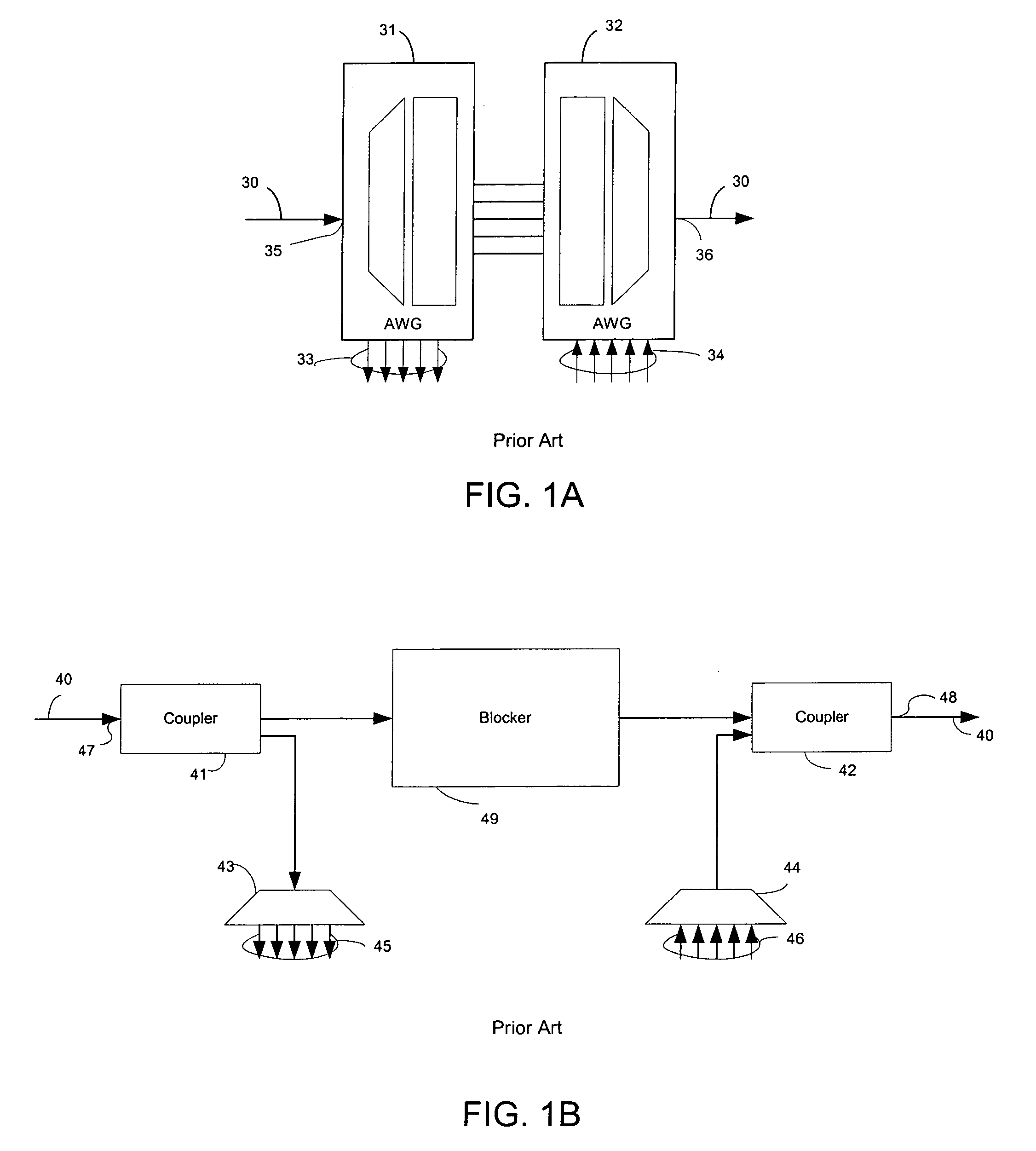
[0012] An appreciation of the present invention and the challenges facing reconfigurable add / drop multiplexers may be gained by a review of designs of current and past add / drop multiplexers. In passing, it should be noted that the term, “multiplexer,” is used in optical communication systems to loosely cover devices and combination of devices at different levels of complexity and organization. For example, add / drop multiplexers which are the subject of the present invention often contain constituent elements which are also termed “multiplexers” (or demultiplexers). These multiplexer elements are often interferometric in fundamental nature, and internally may be Mach-Zehnder interferometers, Fabry-Perot interferometers, arrayed waveguide gratings, devices based on crystal-based Fourier filter technology, etc. For purposes of clear, exposition, such constituent elements are called multiplexer elements below.

[0013] Add / drop multiplexers have drop and add functions, and a third functio...


PUM


Abstract

A reconfigurable WDM add / drop multiplexer and its method of operation at an add / drop node on an optical fiber carrying a plurality of WDM signals is described. The WDM add / drop multiplexer has a coupler and a demultiplexer element dropping WDM signals from the optical fiber to a plurality of drop terminals, and a wavelength-selective switch adding WDM signals from a plurality of add terminals onto the optical fiber. The coupler splits the WDM signals received from the optical fiber and passes the split WDM signals to the first and second output terminals. The demultiplexer element separates the split WDM signals at the plurality of drop terminals. The wavelength-selective switch, which has an input terminal for connection to the second coupler output terminal and an output terminal for connection to the optical fiber, selectively adds WDM signals on the plurality of add terminals to the optical fiber responsive to control signals.

Description

BACKGROUND OF THE INVENTION [0001] The present invention is related to WDM (Wavelength Division Multiplexing) optical systems and, more particularly, to systems and methods for adding and dropping WDM communication channels in WDM systems. [0002] In WDM systems, multiple optical signals having different wavelengths share an optical fiber, each wavelength defining a particular communication channel. This technique has many advantages in implementing optical communication systems including increased capacity and the ability to use passive optical components to redirect a portion of the data flowing along the fiber for processing at an intermediate node. [0003] A representative WDM system may include multiple nodes connected to one another by optical fiber. For example, the nodes may be connected in a ring. Each node typically uses only certain wavelengths (also referred to herein as WDM channels) for transmission and reception and leaves the other wavelengths untouched. A WDM add / drop...

Claims


Application Information

Patent Timeline
IPC IPC(8): H04J14/02
CPCH04J14/0204H04J14/0205H04J14/0212H04J14/0213H04J14/0219H04J14/0221H04Q11/0005H04Q2011/0075
Inventor GERSTEL, ORNANPICIACCIA, STEFANOMACCHI, MAUROCASANOVA, MAURO RUDIJOHNSON, RONALD
Owner CISCO TECH INC
Learn More