
Bodily fluid analysis system

a fluid analysis and fluid technology, applied in the direction of chemical methods analysis, chemical indicators, instruments, etc., can solve the problems of preventing the filtering that the prior art believed was necessary, and achieve the effect of eliminating the risk of cross-contamination, accurate test results, and greater control over the vertical flow of samples

Inactive Publication Date: 2006-03-23
POLYMER TECH SYST
View PDF40 Cites 31 Cited by
  • Summary
  • Abstract
  • Description
  • Claims
  • Application Information

AI Technical Summary

Benefits of technology

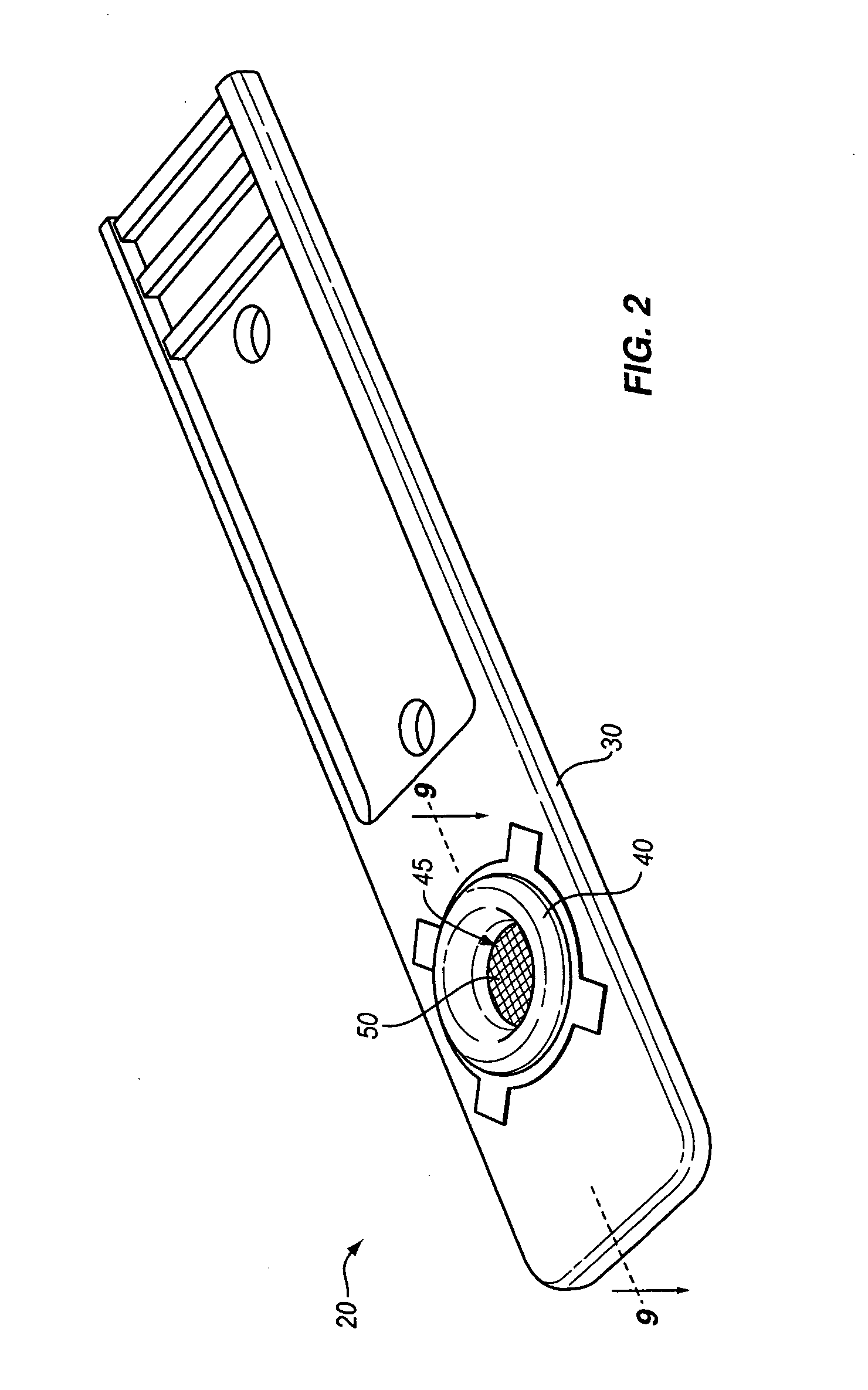
[0012] The present invention provides a solution to the above problems by providing a strip holder that includes a holder base that forms a well that essentially completely encircles the test strip element, and a cover that uniformly contacts the test strip element about the periphery of the element, with the test strip element secured in the well between the cover and base. In this way, stresses that can damage the strip element are avoided. This also prevents leaching, but at the same time impedes lateral flow except for the initial lateral flow that distributes the fluid across the strip, and thus impedes filtering that the prior art believed was necessary. This has lead to a complete rethinking of how a test strip should operate, as discussed in the following.
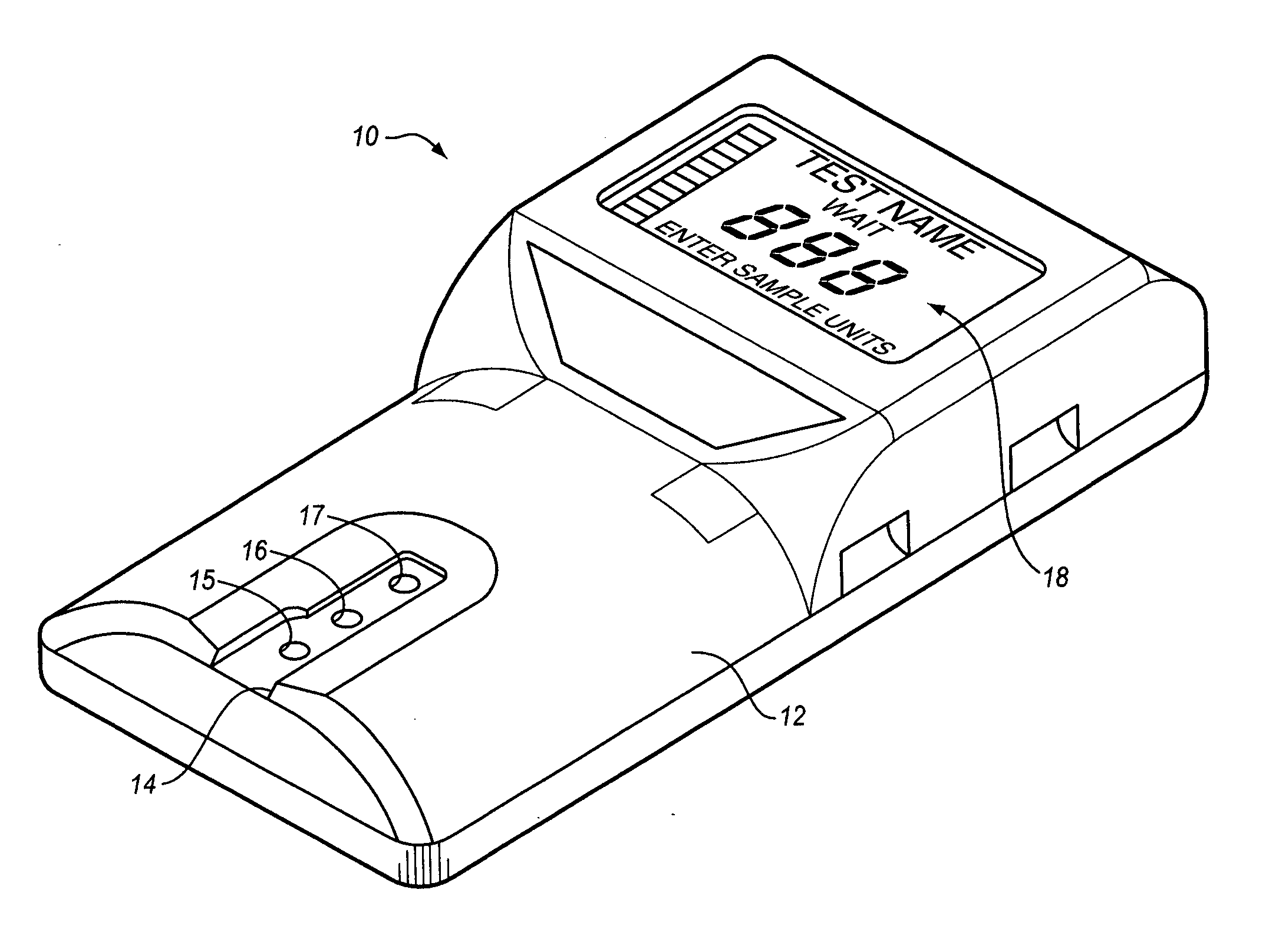
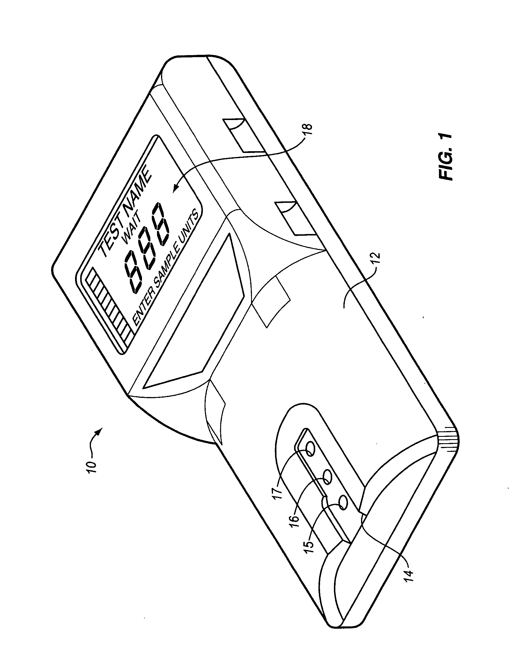
[0017] In a further aspect, the invention provides a system for determining a characteristic of a bodily fluid, the system being portable and of a size that can be easily held in a human hand, the system comprising: a test strip containing a reagent capable of interacting with the bodily fluid to determine the characteristic; and a test strip holder comprising: a test holder base having a sensor port communicating with the test strip; a test holder cap having a sample port communicating with the test strip, the test holder cap secured to the test holder base with the cap and base completely enclosing the test strip except for the ports. Preferably, the test strip is held between the cap and the base. Preferably, the test strip is compressed between the cap and the base. Preferably, the test strip covers the sensor port and prevents fluid from passing through the sensor port. Preferably, the bodily fluid is blood and the characteristic comprises the concentration of high density lipoproteins or low density lipoproteins in the blood.
[0024] The invention further provides a method of determining a characteristic of a selected one of a plurality of analytes in a bodily fluid, the method comprising: providing the bodily fluid containing the selected analyte and one or more non-selected analytes; reacting the selected one of the analytes with a reactant to provide a colorimetric indication of the characteristic; and, prior to the reacting, preventing the non-selected analytes from participating in the reaction, without precipitating the non-selected analytes.
[0025] One benefit achieved by the dry strip architecture of the present invention is that the performance of the strip is essentially volume independent. Since the test strip architecture eliminates the risk of cross-contamination, once the bottom layer of the test strip is saturated, the sample flow stops. Thus, the present invention can accommodate a blood sample as large or larger than the test well. On the other side of the spectrum, the present invention accommodates a sample size essentially as small as the volume of the bottom reaction layer. The present strip architecture limits the fluid expansion area so that the vertical column can be limited to nearly the diameter of the viewing window at the base of the strip. In the preferred embodiment of the invention, the test strip architecture can accept a sample volume as small as 4 ml to as large as 40 ml, while still delivering accurate test results.
[0026] Another benefit of the present invention is that the test strip architecture provides greater control over the vertical flow of the sample. As explained above, once the bottom layer of the strip is saturated, sample flow stops which means that the flow of red blood cells also stops. When the flow of RBCs stops, there is no further need for capturing the RBCs. This aspect of the present invention allows the use of a less efficient RBC capturing layer, since the sample flow physics will stop the flow of RBCs at the optimum point.
[0027] It is one object of the invention to provide a holder for a diagnostic test strip that can maintain the integrity of the test strip without risking damage to it. Another object is to provide a test strip assembly architecture that can improve the accuracy of the diagnostic output. These and other objects and benefits of the invention will become apparent from the following written description and accompanying figures.

Problems solved by technology

This also prevents leaching, but at the same time impedes lateral flow except for the initial lateral flow that distributes the fluid across the strip, and thus impedes filtering that the prior art believed was necessary.

Method used


Image

  • Bodily fluid analysis system
  • Bodily fluid analysis system
  • Bodily fluid analysis system

Examples


Embodiment Construction

[0045] For the purposes of promoting an understanding of the principles of the invention, reference will now be made to the embodiments illustrated in the drawings and described in the following written specification. It is understood that no limitation to the scope of the invention is thereby intended. It is further understood that the present invention includes any alterations and modifications to the illustrated embodiments and includes further applications of the principles of the invention as would normally occur to one skilled in the art to which this invention pertains. It should also be understood that, in accordance with the patent law, the drawings are not intended to be precise engineering drawings of the invention, but rather are only intended to illustrate the invention. For example, the scale of the drawings and relative size of the various parts are generally altered so as to better illustrate the invention within the constraints of a written document such as this.

[0...


PUM

PropertyMeasurementUnit
volumeaaaaaaaaaa
volumeaaaaaaaaaa
pore sizeaaaaaaaaaa

Abstract

A bodily fluid analyzer including a test strip holder comprising a base and a snap-on cover which completely enclose the test strip except for a sample port in the cover and a sensor port in the base. The test strip is compressed between the base and cover in a sample container having a well-defined sample volume. The test strip comprises a woven dispersement layer, a depth filter containing a reagent, an asymmetrical membrane containing additional reagent, and a colorimetric detection membrane in a vertical stack. The red blood cells are removed from the colorimetric detection area by slowing their vertical movement and stopping flow when the detection membrane is saturated. A minimum value of the reflectance in a color range is used to determine a characteristic of the bodily fluid.

Description

CROSS-REFERENCE TO RELATED APPLICATIONS [0001] This application is a continuation-in-part of U.S. patent application Ser. No. 10 / 962,272 filed Oct. 11, 2004, which claims the benefit of U.S. Provisional Application No. 60 / 541,681 filed Feb. 3, 2004. This application also claims the benefit of U.S. Provisional Application No. 60 / 602,210 filed Aug. 17, 2004. All of the above patent applications, both provisional and non-provisional, are hereby incorporated by reference to the same extent as though fully contained herein.BACKGROUND OF THE INVENTION [0002] 1. Field of the Invention [0003] The invention in general relates to bodily fluid analysis systems including a disposable test strip, with particular application to on-site testing of particular analytes in blood. [0004] 2. Statement of the Problem [0005] The level of certain analytes in blood and other body fluids is often used to diagnose disease, determine disease risk factors, monitor the course of a therapy, or determine the pres...

Claims


Application Information

Patent Timeline
Patent Type & Authority Applications(United States)
IPC IPC(8): G01N31/22
CPCG01N21/78G01N21/8483G01N33/52G01N33/526G01N2800/044G01N2021/8494G01N2021/8654G01N2201/0221G01N33/92
Inventor LAWRENCE, GREGORY M.
Owner POLYMER TECH SYST
Learn More