
Liquid ejection head inspection method and printer device

a liquid ejection head and inspection method technology, applied in the direction of printing, other printing apparatus, etc., can solve the problems of failure or significant change in characteristics at some piezoelectric elements, problems such as adhesion problems, and problems in the ejection of ink, so as to suppress the frequency of breakdown, improve the effect, and reduce the frequency of breakdown

Inactive Publication Date: 2006-03-23
FUJIFILM BUSINESS INNOVATION CORP
View PDF0 Cites 8 Cited by
  • Summary
  • Abstract
  • Description
  • Claims
  • Application Information

AI Technical Summary

Benefits of technology

[0010] The present invention has been devised in consideration of the circumstances described above, and will provide a liquid ejection head inspection method which is capable of suppressing occurrences of breakdowns over time and the like in piezoelectric elements provided at a liquid ejection head, and a printer device.
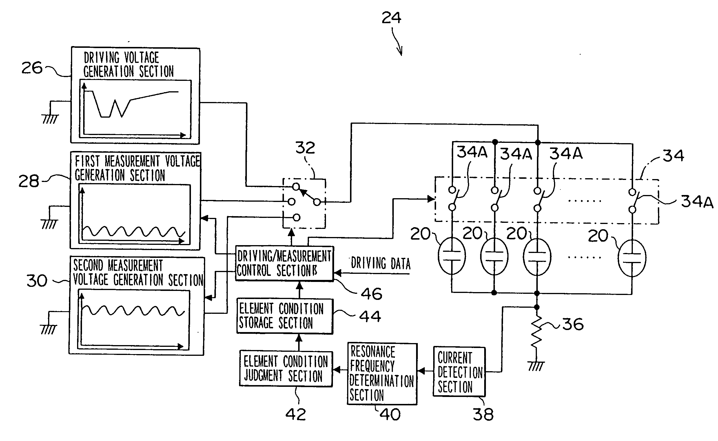
[0016] In the second aspect of the present invention, the information representing the piezoelectric elements that are expected to be susceptible to faults over time, which have been detected by the liquid ejection head inspection method of the first aspect, is stored at the storage section. The driving control section controls driving of the liquid ejection head in accordance with the information stored in the storage section, so as to lower frequencies of occurrence of driving of the piezoelectric elements for which susceptibility to failure over time is anticipated. Thus, it is possible to suppress occurrences of breakdowns and the like over time of the piezoelectric elements provided at the liquid ejection head.
[0018] At the printer device of the third aspect of the present invention, the measurement section is provided. The measurement section respectively applies the first voltage to the individual piezoelectric elements and measures the resonance frequencies, and respectively applies the second voltage, which is higher than the first voltage, to the individual piezoelectric elements and measures the resonance frequencies. On the basis of the resonance frequencies measured when the first voltage applied by the measurement section and the resonance frequencies measured when the second voltage applied, the detection section detects the piezoelectric elements that are expected to be susceptible to faults over time. The storage section stores the information representing the piezoelectric elements for which susceptibility to failure over time is anticipated, which have been detected by the detection section. Hence, the driving control section controls driving of the liquid ejection head in accordance with the information stored in the storage section so as to lower frequencies of occurrence of driving of the piezoelectric elements that are likely to be susceptible to failure over time. Thus, similarly to the second aspect, it is possible to suppress occurrences of breakdowns and the like over time of the piezoelectric elements provided at the liquid ejection head.
[0019] According to the structures described above, the present invention has an excellent effect in that it is possible to suppress occurrences, over time, of faults and the like in piezoelectric elements provided at a liquid ejection head.

Problems solved by technology

However, among the numerous piezoelectric elements which are joined on, there may be piezoelectric elements with joining problems, piezoelectric elements which contain cracks, and the like.
Hence, such piezoelectric elements may lead to problems in the ejection of ink.
For example, Japanese Patent Application Laid-pen (JP-A) No. 11-4175 has disclosed a technology in which an impedance analyzer is connected to each nozzle, a characteristic frequency (resonance frequency) of the piezoelectric element that is provided in correspondence with the nozzle is measured, and any piezoelectric element that exhibits a characteristic frequency which is offset from a characteristic frequency of piezoelectric elements whose adhesion conditions are normal is judged to have an adhesion problem.
However, even if the inspections described above are carried out during fabrication of printer devices and / or during distribution, and it has been confirmed for the recording heads in the printer devices that resonance frequencies of individual piezoelectric elements are contained within a certain range, during continuing use of the printer device, there may be faults or significant changes in characteristics at some of the piezoelectric elements over time.
Piezoelectric elements that break down or undergo major changes in characteristics over time (that is, short-lifespan piezoelectric elements) are thought to result from slight faults in joining conditions during fabrication of the recording head, or the inclusion of slight cracks.
However, in conventional inspection of a recording head, it is difficult to detect piezoelectric elements that will break down or exhibit major changes in characteristics over time, even if a threshold value for the resonance frequency is adjusted, and thus the accuracy of the inspection is actually insufficient.

Method used


Image

  • Liquid ejection head inspection method and printer device
  • Liquid ejection head inspection method and printer device
  • Liquid ejection head inspection method and printer device

Examples


Embodiment Construction

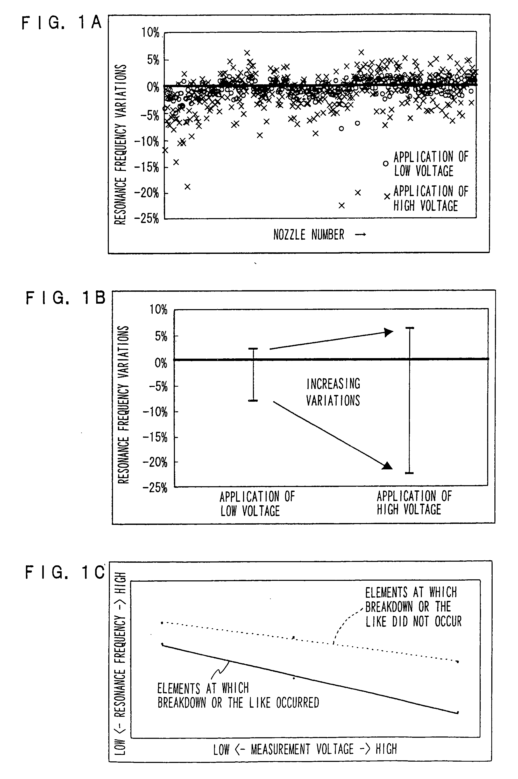
[0032] In a liquid ejection head inspection method according to the present invention, at a liquid ejection head which is equipped with plural nozzles at which piezoelectric elements are provided and which ejects recording liquid droplets from the individual nozzles in accordance with the application of a driving signal voltage to the individual piezoelectric elements, a first voltage is respectively applied to the individual piezoelectric elements and resonance frequencies are measured, a second voltage, which is higher than the first voltage, is respectively applied to the individual piezoelectric elements and resonance frequencies are measured and, on the basis of the resonance frequencies at the times of application of the first voltage and the resonance frequencies at the times of application of the second voltage, detects piezoelectric elements which are likely to be susceptible to failure over time.

[0033] Herein, a magnitude (any of a maximum voltage, an average voltage, and...


PUM


Abstract

The present invention provides a method for inspecting of a liquid ejection head which is equipped with plural nozzles at which piezoelectric elements are provided and which ejects recording liquid droplets from the individual nozzles in accordance with application of a driving signal voltage to the individual piezoelectric elements. In the method, a first voltage is applied to each individual piezoelectric element for measuring a resonance frequency of the individual piezoelectric element, a second voltage which is higher than the first voltage is applied to the individual piezoelectric element for measuring a resonance frequency of the individual piezoelectric element, and on the basis of the resonance frequencies at the times of application of the first voltage and the resonance frequencies at the times of application of the second voltage, piezoelectric elements that are likely to be susceptible to failure over time are detected.

Description

CROSS-REFERENCE TO RELATED APPLICATION [0001] This application claims priority under 35 USC 119 from Japanese Patent Application No. 2004-275346, the disclosure of which is incorporated by reference herein. BACKGROUND OF THE INVENTION [0002] 1. Field of the Invention [0003] The present invention relates to a liquid ejection head inspection method and a printer device, and more particularly relates to a method for inspecting a liquid ejection head in which plural nozzles provided with plural piezoelectric elements are provided, the liquid ejection head being configured to eject droplets of recording liquid from the individual nozzles in accordance with the application of driving voltages to the individual piezoelectric elements, and to a printer device in which this liquid ejection head inspection method can be applied. [0004] 2. Description of the Related Art [0005] Inkjet recording systems record images of text, photographs and the like on recording media (sheets, papers or the lik...

Claims


Application Information

Patent Timeline
Patent Type & Authority Applications(United States)
IPC IPC(8): B41J29/38
CPCB41J2/04581B41J2/0451
Inventor YAGI, TAKASHI
Owner FUJIFILM BUSINESS INNOVATION CORP
Learn More