Systems and methods for modular instrument design and fabrication

a modular instrument and design technology, applied in the direction of girders, mounting boards, electrical apparatus construction details, etc., can solve the problems of reducing affecting the service life of the instrument, so as to prevent torsional movement

Inactive Publication Date: 2006-03-23
AGILENT TECH INC
View PDF31 Cites 10 Cited by
  • Summary
  • Abstract
  • Description
  • Claims
  • Application Information

AI Technical Summary

Benefits of technology

[0005] Embodiments of systems and methods for modular instrument or system design and fabrication may employ a plurality of members adapted to be interlocked with one another and anchored to an instrument housing structure. Each of these integral members has a central elongated body portion, which might have a generally square cross section. Cross-holes may extend transversely through the central body portion, in at least one direction. Bead portions extend along, at least, a pair of corners of the body, to a point spaced apart from an end of the body portion this may result in a key portion of the body being formed at an end of the body. A channel portion is defined by a surface of the body and a pair of the beads, the channel is adapted to register with a key of another member. A fastener receptive threaded orifice is defined in the end of the body. This orifice may be defined by a central cannula extending through a length of the body. Embodiments of the present systems and methods also employ fasteners extending though a cross-hole of a first of the members to be received by an end orifice of a second of the members, interlocking the first and second members and preventing torsional movement by the members relative to one another.

Problems solved by technology

This is time consuming and costly.
Not only is the cost of a small run of custom parts expensive, overhead related to these custom or small production runs is relatively high as the resulting instrument and its parts require many of the overhead processes and procedures that a mass produced product requires.
Also, it takes time to fabricate custom parts and the time required to gather all of the custom produced parts may also present problems, particularly where multiple vendors are involved, as is often the case.
When prototyping, or at the beginning of fabrication, it is often found that a custom piece is missing or not made as specified.
At this time, it might be determined that a redesign of the instrument is necessary causing further delay and cost.
In such cases, it may be necessary to have one or more new pieces fabricated, causing a halt, or at least a delay, in the prototyping process or in product production.
Custom designed instruments often have undesirable qualities.
For example the final product may be a relatively “closed” system that requires tortuous cable routing and an inflexibility limiting the ability to make changes or enhancements to the instrument.
Custom produced instruments are often cluttered with long cable runs required or with cables routed through sheet metal decks or the like.
Additionally, design may be problematic in that the instrument designers may be designing an instrument that uses components that the designers do not have on-hand, and for which the designers may not know the actual, final dimensions or configuration.
However, such frames are typically configured for use in a single instrument design, are costly, and time consuming to fabricate.
Problematically, custom fabricated sheet metal or manual drilling of sheet metal elements must be used to mount PCBs for custom instrument fabrication.

Method used


Image

  • Systems and methods for modular instrument design and fabrication
  • Systems and methods for modular instrument design and fabrication
  • Systems and methods for modular instrument design and fabrication

Examples


embodiment 600

[0025] Embodiments of the present systems and methods provide a strong structure for mounting instrument components. However, in accordance with embodiments of the present systems and methods members may be doubled, as shown in FIG. 6, tripled, or likewise combined, to support heavy parts mounted thereto. Two-member-truss embodiment 600 may be constructed from cord members 601 and 602, joined by spanning strut-tie members 603-606 and secured by screws 607. Components of an instrument may be secured to or on such a truss, such as by using fasteners and stand offs, or in other manners discussed herein or as known in the art, for deployment in the instrument.

[0026] Frames built using the present members may be used to mount components and circuit boards and these frames may in turn be mounted in a chassis, such as a housing or casing, which may in turn be covered or deployed as a part of a rack system or the like. In accordance with embodiments of the present systems and methods, PCBs ...

embodiment 700

[0030] In accordance with embodiments of the present systems and methods members may be deployed for use as a card guide. FIG. 7 is a perspective view of embodiment 700 using embodiments of members 701 and 702 of the present systems to act as a PCB or card guide. Illustrated card guide 700 is comprised of a pair of spaced apart members 701 and 702 disposed in relation to a card location in an instrument, spaced apart a distance appropriate to receive edges of card 703 and support the card in a deployed configuration in the instrument, for example, in a card slot of another PCB, such as a processor board, of the instrument.

[0031] In accordance with embodiments of the present systems and methods members may be deployed in a hinged swing assembly configuration. FIG. 8 is a perspective view of an embodiment using embodiments of the members of the present systems to act as hinged circuit board mounting structure 800. Members 801-815 are shown interconnected in an arrangement to support a...

embodiment 1000

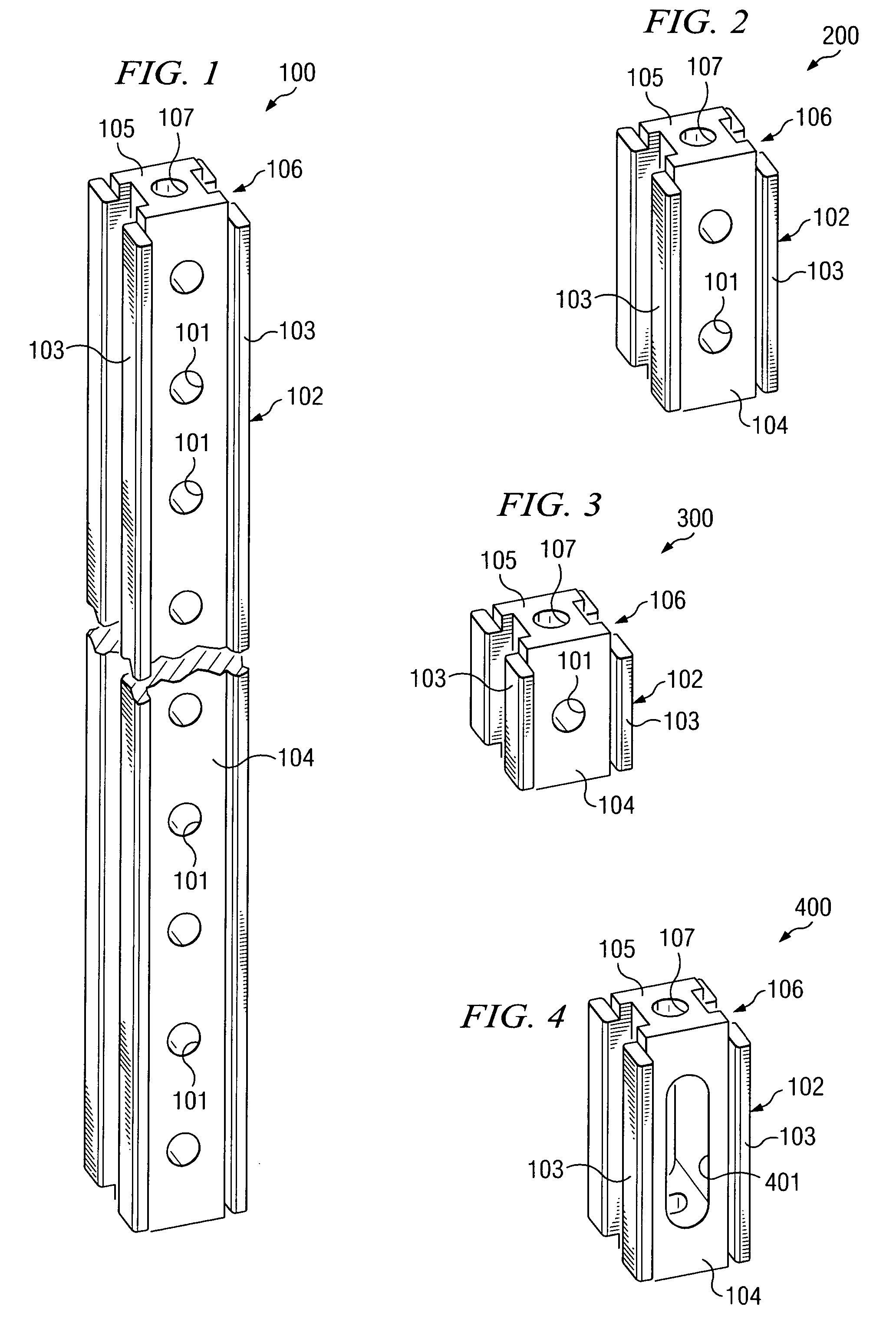
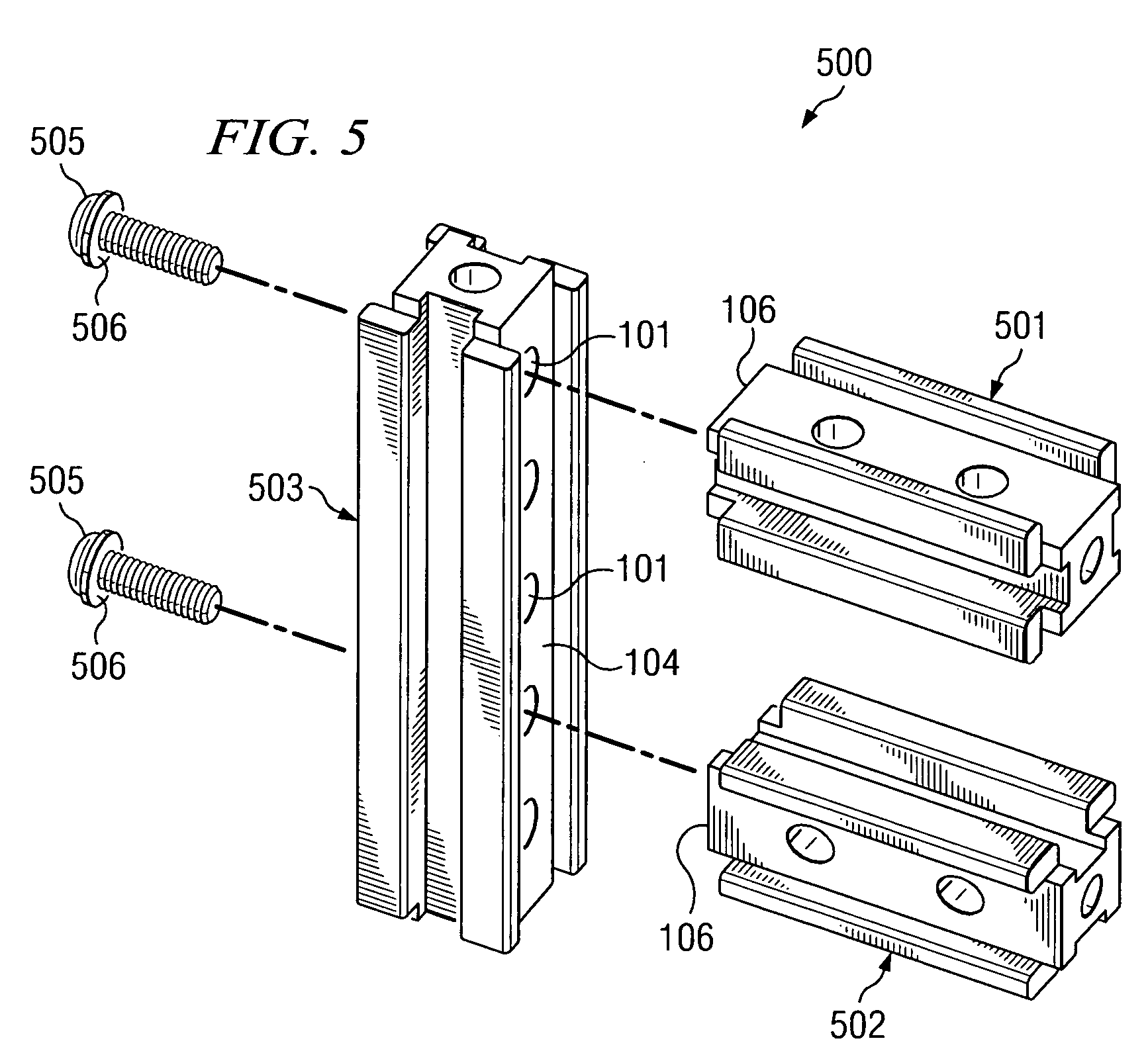
[0035] A beam member framework may be assembled outside of an instrument housing and components mounted to this framework, which may them be anchored in the instrument housing. Alternatively, the beam member framework may be built within the housing and then the components mounted to the framework. Embodiment 1000 of the present methods illustrated in the flow chart of FIG. 10 might be used to deploy embodiments of the present systems, such as illustrated in FIG. 9. At 1001 first beam members to be disposed in the instrument housing structure, such as members 905 and 906 of FIG. 9, may be interlocked with second beam members to be disposed in the instrument housing, such as beam members 902, 903 and 913 of FIG. 9, to provide a framework. The members may be interlocked at 1001 by keying an end (key 106) of a first beam member with a channel (104) defined by a second beam member at 1002; receiving a fastener through a cross-hole (101) of the second member into an end orifice (107) of ...


PUM


Abstract

Modular component mounting systems and methods employ a plurality of members adapted to be interlocked with one another and anchored to an instrument housing. Each of the members comprises a central elongated body, cross-holes extending transversely through the body, beads extending along corners of the body to a position spaced apart from an end of the body defining a key at the end of the body, a channel defined by a surface of the body and a pair of the beads to receive and register with a key of another member, and a fastener receptive orifice defined in the end of the body. A fastener extends though one of the cross-holes of a first member to be received by an end orifice of a second member, interlocking the members and preventing torsional movement by the members relative to one another.

Description

BACKGROUND OF THE INVENTION [0001] Many electronic systems, instruments, and the like must be custom designed and / or fabricated. Such instruments may include processor-based systems, communications equipment, networking equipment, switch matrixes, testing equipment, and the like. Such equipment may be developed to meet specific requirements of a customer and may be one of a kind or small production runs, such as of fifteen or fewer units. However, these same customers expect, or at least desire, an inexpensive solution to such custom applications, provided in a timely manner. [0002] Traditionally, even small run jobs are treated as truly custom jobs that involve custom designing each part including housing and mounting sheet metal, machined parts and the like. This is time consuming and costly. Not only is the cost of a small run of custom parts expensive, overhead related to these custom or small production runs is relatively high as the resulting instrument and its parts require m...

Claims


Application Information

Patent Timeline
Patent Type & Authority Applications(United States)
IPC IPC(8): E04B2/74E04C3/04E04C3/06E04C3/28H05K7/14
CPCE04C3/06E04C3/28E04C2003/0439H05K7/1425E04C2003/0465H05K7/1418E04C2003/0452F16S3/00F16S3/08H05K7/1422H05K7/18H05K7/183
Inventor YEUNG, HUBERT K.
Owner AGILENT TECH INC
Why Eureka
Try Eureka