Process and installation for the treatment of DSO

a technology of disulfide hydrogenation and installation, which is applied in the direction of liquefaction, solidification, lighting and heating apparatus, etc., can solve the problems of mercaptan extraction only slightly, the need for lpg treatment, and the inability to extract mercaptan from propane and butane cuts using molecular sieves

Active Publication Date: 2006-03-16
TOTAL PUTEAUX FR
View PDF5 Cites 26 Cited by
  • Summary
  • Abstract
  • Description
  • Claims
  • Application Information

AI Technical Summary

Benefits of technology

[0099] One of the advantages of the invention is to increase the H2S content of the flow feeding the sulfur production unit 23. Thus, as indicated above, this unit is preferentially fed by an acid gas having a minimal H2S content, in order to obtain a sufficiently high flame temperature. Further, it is known that, according to the prior art, one of the possible ways to eliminate the DSO consists in transforming it by incineration into SO2, and after washing the smoke, sending the SO2 thus recuperated into the sulfur production unit. However, the sulfur contained in the DSO cannot now participate in raising the flame temperature because it is already in an oxidized form upon arrival from the sulfur production unit. By contrast, in the process according to the invention the sulfur content in the DSO arrives at the sulfur production unit in a form of H2S, which actively maintains the flame temperature.

Problems solved by technology

However, the mercaptans are only slightly extracted when classical processes of de-acidification, that are most often washings with amine solutions, are used.
These commercially unacceptable levels make necessary the treatment of the LPG.
At such high content levels, mercaptan extraction from the propane and butane cuts cannot be done using molecular sieves.
However, mainly in gas treatment plants, it happens that such cuts are not available, thus making then necessary the treatment of DSO in situ.
The quantity of DSO that is possible to incinerate jointly with H2S is therefore limited and often inferior to that produced during the treatment of LPG.
Today this method has not yet been used industrially.
This technique, however, presents the inconvenience of operating in a very corrosive medium and of requiring the use of noble metallurgical products for the equipment, for example, stainless steel.

Method used


Image

  • Process and installation for the treatment of DSO
  • Process and installation for the treatment of DSO
  • Process and installation for the treatment of DSO

Examples


example

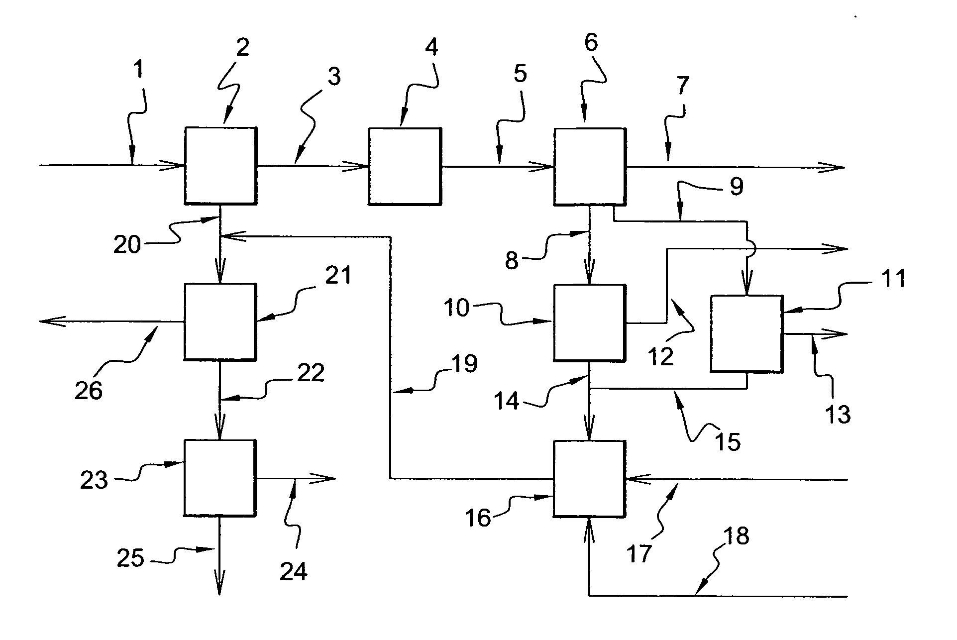
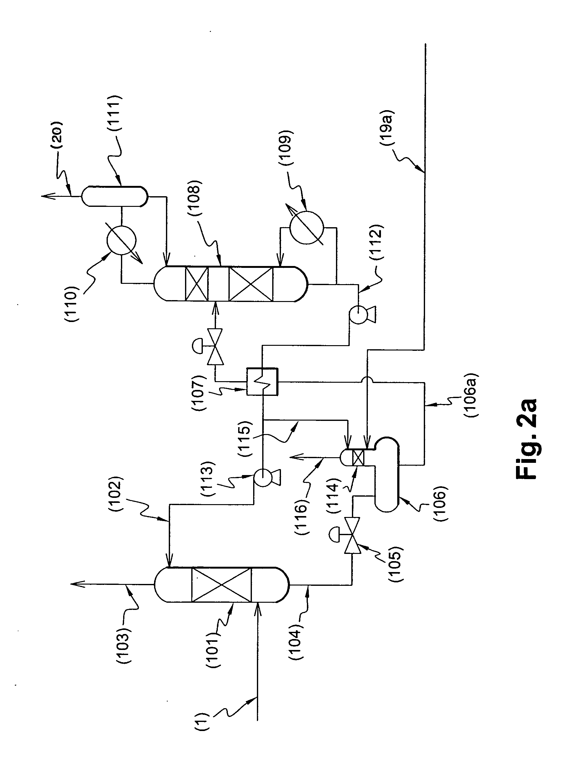
[0119] The example given below corresponds to the process according to the first alternative of the second embodiment.

[0120] The natural gas 1 is treated successively in the units 2 and 4 and is liquefied in the unit 6. During liquefaction, the propane and the butane are extracted and the mercaptans are consequently simultaneously condensed. They are treated by washing with sodium hydroxide in units 10 and 11 and the DSO is produced at 14 and 15. After hydrogenation in 16 where the natural gas is used as a diluent to limit the temperature rise, the DSO transformed into H2S is sent to the entry of the enrichment unit 21. The liquefied natural gas 7 meeting the sulfur content specifications is produced directly by condensation of mercaptans without supplementary treatment.

[0121] The material balance given below (Table) allows one to follow the migration of the sulfur contained in the mercaptans. This Table gives the composition and the rates of the principal flows. Certain flows are...


PUM

PropertyMeasurementUnit
Fractionaaaaaaaaaa
Fractionaaaaaaaaaa
Flow rateaaaaaaaaaa

Abstract

The invention relates to a process for the treatment of gas containing mercaptans and acid gases, comprising the following steps: (1) separating the acid gases from the said gas and obtaining a sweetened gas and the flow of acid gases containing H2S; (2) reacting the H2S thus obtained in step (1) according to the Claus reaction; (3) concentrating themercaptans in at least one cut of the said sweetened gas; (4) extracting the mercaptans of the said cut; and further comprising: (5) transforming the mercaptans into dialkyl-disulfide (DSO); (6) hydrogenating DSO into H2S; and (7) reacting the H2S thus obtained at step (6) according to the Claus reaction. The invention also relates to an installation for carrying out this procedure.

Description

FIELD OF THE INVENTION [0001] The present invention relates to a process for the hydrogenation of disulfides (DSO) resulting from the transformation of the mercaptans contained in Liquefied Petroleum Gas (LPG), into hydrogen sulfide and hydrocarbons and their conversion in Claus units. The process applies equally well to natural gas liquefaction plants as to natural gas or refinery gas treatment plants BACKGROUND ART [0002] A natural gas extracted from subsoil is, under normal conditions of temperature and pressure, a mixture of gaseous hydrocarbons. Typically, a natural gas is, for example constituted of 75% methane, 20% other gaseous hydrocarbons, dominantly ethane, and 5% acid gases, namely carbon dioxide (CO2) and hydrogen sulfide (H2S). Liquefied Petroleum Gas (GLP) are generally mainly formed of three- or four-carbon-chain gaseous hydrocarbons, i.e. propane, butane and their unsaturated versions propene and butene. Accompanying these components are traces of contaminants, esse...

Claims


Application Information

Patent Timeline
IPC IPC(8): C01B17/02B01D50/00C10L3/12
CPCC10L3/12
Inventor CHRETIEN, DENIS
Owner TOTAL PUTEAUX FR
Why Eureka
Try Eureka