
Marine forest structure

a forest structure and structure technology, applied in the field of marine forest structure, can solve the problems of high cost, poor workability, complicated work, etc., and achieve the effects of reducing weight, low cost, and swarming effect of fishes

Inactive Publication Date: 2006-03-16
KANEDA KENSETABU
View PDF7 Cites 9 Cited by
  • Summary
  • Abstract
  • Description
  • Claims
  • Application Information

AI Technical Summary

Benefits of technology

[0017] The marine forest structure of the invention is to provide a technique of a structure which can be constructed in a simple structure in which pillar bodies are raised only, and in which pillar bodies having different, heights are arranged in a predetermined order so that physical-chemical, biological continuity of an inhabiting place / space and an external space is ensured by a moderate shifting zone of a bright part and a shadow part formed by the pillar bodies, so that the volume of the inhabiting place / space of fishes and the like can be made large.
[0035] In the fourth invention of the invention, as described above, since the pillar bodies raised from the base are constituted by scrap wood of telegraph poles, or thinning wood of mountains and forests, scrap wood can be effectively utilized, and a large amount of structures can be produced at extremely low cost. Particularly, scrap wood of telegraph poles are suitable for growing of seaweeds, and seaweeds can be allowed to grow thickly only by making the structure submerge into and disposed in the sea for a predetermined period of time if natural seaweeds are growing thickly in the vicinity thereof. Thinning wood can be utilized as an inhabiting place of a small animals such as Gammarid and the like which become feed for fishes, and swarming effect of fishes can be expected.

Problems solved by technology

In the techniques of Japanese Patent Nos. 2824232 and 2905432, since the carrying bases to which seaweed species fungi are allowed to adhere in advance have to be attached and fixed to the pillar bodies and to the stick-like bodies, respectively, in a branching manner, problems arise in that the workability is extremely poor and that the cost becomes high.
Further, in the technique of JP-A No. 2000-69878, since seaweed species fungi have to be planted on the pillar body standing at the central portion of the concrete base formed into the cross-shape by a predetermined means, similarly to Japanese Patent Nos. 2824232 and 2905432, problems arise in that the work is complicated and that the cost becomes high.
The technique of JP-A No. 2000-69878 has problems that the plurality of special pillar bodies independently standing by buoyancy have to be employed, that the lower ends of these pillar bodies have to be swingably attached and fixed to the base made of stone, employing the extremely complicated coupling means, that the structure thereof is complex, and that the work is troublesome in the case where this structure is realized.
The technique of JP-A No. 7-317042 has problems that the plural pillar bodies, after being coupled mutually through horizontal cross pieces to construct a unit, have to be extended upwardly from the apertures in the concrete heavy base so that the work is complex, although there is a merit that a large number of pillar bodies can be allowed to stand together.
Further, there is one more problem that as the base which supports a large number of units, an extremely heavy concrete base has to be employed.
Accordingly, there is a problem that a base which has a weight heavier than necessary has to be employed and that this base, the pillar bodies upstanding therefrom, and the like have to be securely coupled together.
Further, in the case of a marine forest in which the pillar or stick-like bodies having approximately the same height are raised from the base, there is a problem that shadow portions formed in the sea by these pillar bodies and the like are uniform and lack variety.

Method used


Image

  • Marine forest structure
  • Marine forest structure
  • Marine forest structure

Examples


first embodiment

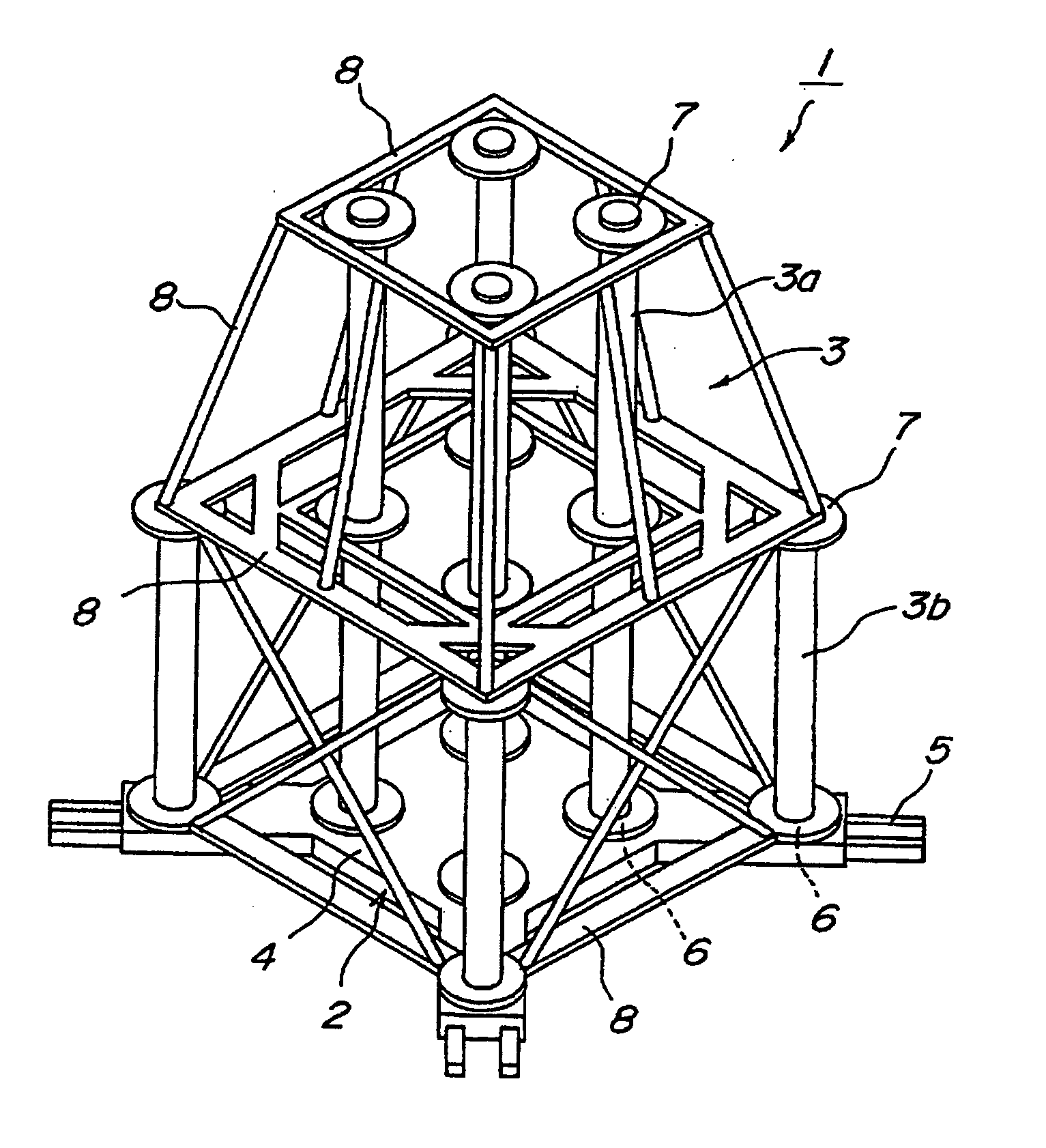
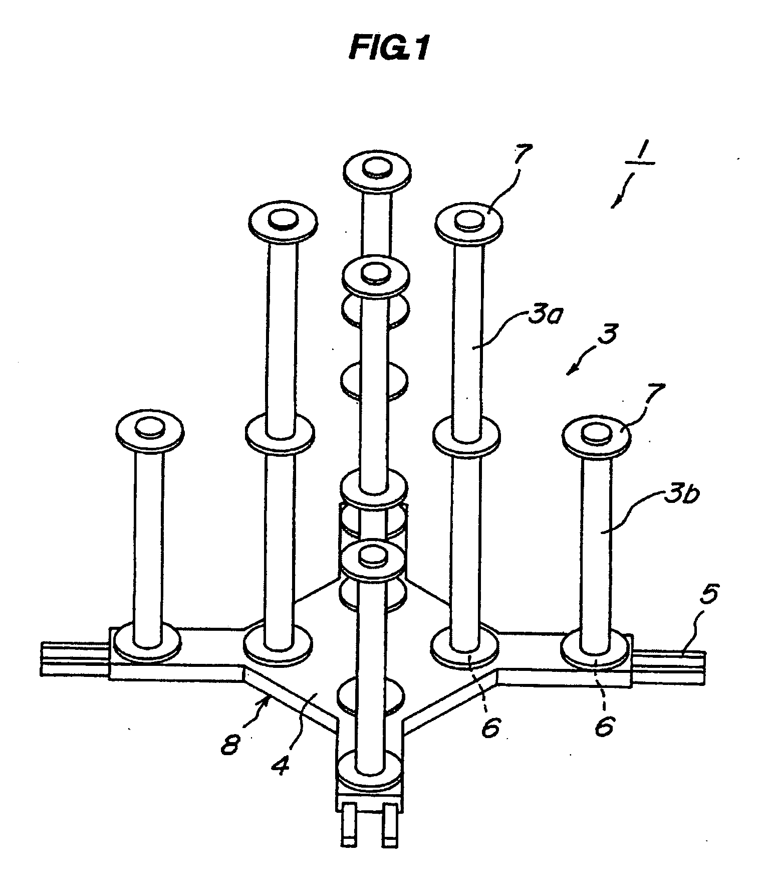
[0048] Referring to FIGS. 1 to 3, a marine forest structure according to the invention will be described. This marine forest structure 1 is basically composed of a base 2 and a plurality of pillar bodies 3 raised from this base 2.

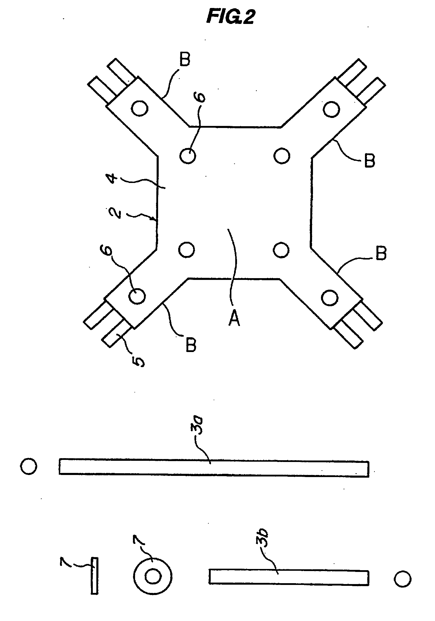
[0049] The base 2 is composed of a rectangular flat plate 4 formed of steel, concrete, or the like and legs 5 protruding from respective corners of this flat plate 4. These legs 5 are formed integrally with the flat plate 4 in advance. These legs 5 plays a role of making the base 2 stable on the bottom of the sea when the marine forest structure 1 is submerged and placed in the sea.

[0050] Holes 6 for raising the pillar bodies 3 respectively are provided in a central part A (central part of the base) and corner parts B (peripheral parts of the base) of the flat plate 4. In the present embodiment, four holes 6 are provided in the central part of the flat plate 4, and one hole 6 is provided on each corner part.

[0051] Steel, concrete, telegraph poles which ha...

second embodiment

[0056] In this second embodiment, pillar bodies 3a raised from the central part of the base 2 have a height of approximately 12 m, and pillar bodies 3b approximately 4 m. Accordingly, the entire height of the marine forest structure 9 is approximately 12.5 m, the bottom side width approximately 12 m, the space volume approximately 330 m3, and the entire weight approximately 36.7 t. This marine forest structure 9 can be effectively employed in a sea area which has a deep depth.

[0057] Referring to FIGS. 5 to 7, a marine forest structure 10 of the third embodiment according to the invention will be described. Although scrap telegraph poles are effectively utilized for the pillar bodies 3 in the above-described first and second embodiments, in the marine forest structure 10 of this third embodiment, thinning wood of mountains and forests is effectively utilized instead of scrap telegraph poles.

third embodiment

[0058] In describing the marine forest structure 10 of the third embodiment with reference to the drawing, pillar bodies 11a are thinning wood whose height is approximately 12 m, and pillar bodies 11b are thinning wood whose height is approximately 4 m. A plurality of pillar bodies 11a are respectively raised from four holes 6 of a central part A (central part of the base) of a flat plate 4 of a base 2, and pillar bodies 11b are raised from holes 6 of corner parts B (peripheral parts of the base) of the flat plate 4. The pillar body 11a raised from the central part A can be constructed by coupling the pillar bodies 11b which has a low height.

[0059] Although the number of pillar bodies 11a, 11b raised from the respective holes 6 changes depending on the diameters of the pillar bodies, generally approximately four to twelve pillar bodies 11a, 11b can be inserted into the respective holes 6 to be raised therefrom. The positions of the lower end portions of the plural pillar bodies 11a,...


PUM


Abstract

The present invention is to provide a marine forest structure by which many kinds of fishes and shellfishes can gather and inhabit and to which useful seaweeds such as of Laminariaceae and the like can adhere to propagate when the structure is submerged and disposed on the bottom of the sea. Provided is a marine forest structure 1 which is composed of a base 2 in which legs 5 are protruded from a peripheral edge of a flat plate 4 in which plural holes 6 are provided in a central part and a peripheral part thereof and two kinds of pillar bodies 3a, 3b whose lengths are different. The marine forest structure is constructed such that a plurality of pillar bodies 3a which has a predetermined height are raised from and fixed to the holes 6 of the flat plate 4 and that pillar bodies 3b which has a height lower than that of the pillar bodies 3a with the predetermined height are raised from and fixed to the plural holes 6 of the periphery of the flat plate 4.

Description

BACKGROUND OF THE INVENTION [0001] 1. Field of the Invention [0002] The present invention relates to a marine forest structure which makes seaweeds grow thickly, in which fishes and shellfishes can settle and propagate, and which is to improve an environment in the sea, and more particularly to a technique of a marine forest structure for which scrap wood can be effectively utilized, which can be installed in a stable state in the sea without being influenced by waves, and which can be assembled easily near the sea where the structure is installed. [0003] 2. Description of the Related Art [0004] Conventionally, as techniques developed for this type of purpose, for example, well known are Japanese Patent No. 2824232, Japanese Patent No. 2905432, Japanese Patent Application Laid-Open (JP-A) No. 9-65795, JP-A No. 2000-69878, JP-A No. 7-317042, and the like. [0005] The technique of Japanese Patent No. 2824232 described above is of a preparation method of a marine forest which is constru...

Claims


Application Information

Patent Timeline
IPC IPC(8): E02B3/06
CPCE02B3/046A01K61/006A01K61/70Y02A40/81A01K61/73
Inventor ARAI, SHOGO
Owner KANEDA KENSETABU
Learn More