
Collimator fabrication

a technology of collimator and fabrication method, which is applied in the direction of instruments, nuclear engineering, and handling using diaphragms/collimeters, etc., can solve the problems of non-redundancy design arrays, and achieve the effect of low error tolerance, precise dimensions and low error toleran

Inactive Publication Date: 2006-03-16
JMP INDS
View PDF75 Cites 5 Cited by
  • Summary
  • Abstract
  • Description
  • Claims
  • Application Information

AI Technical Summary

Benefits of technology

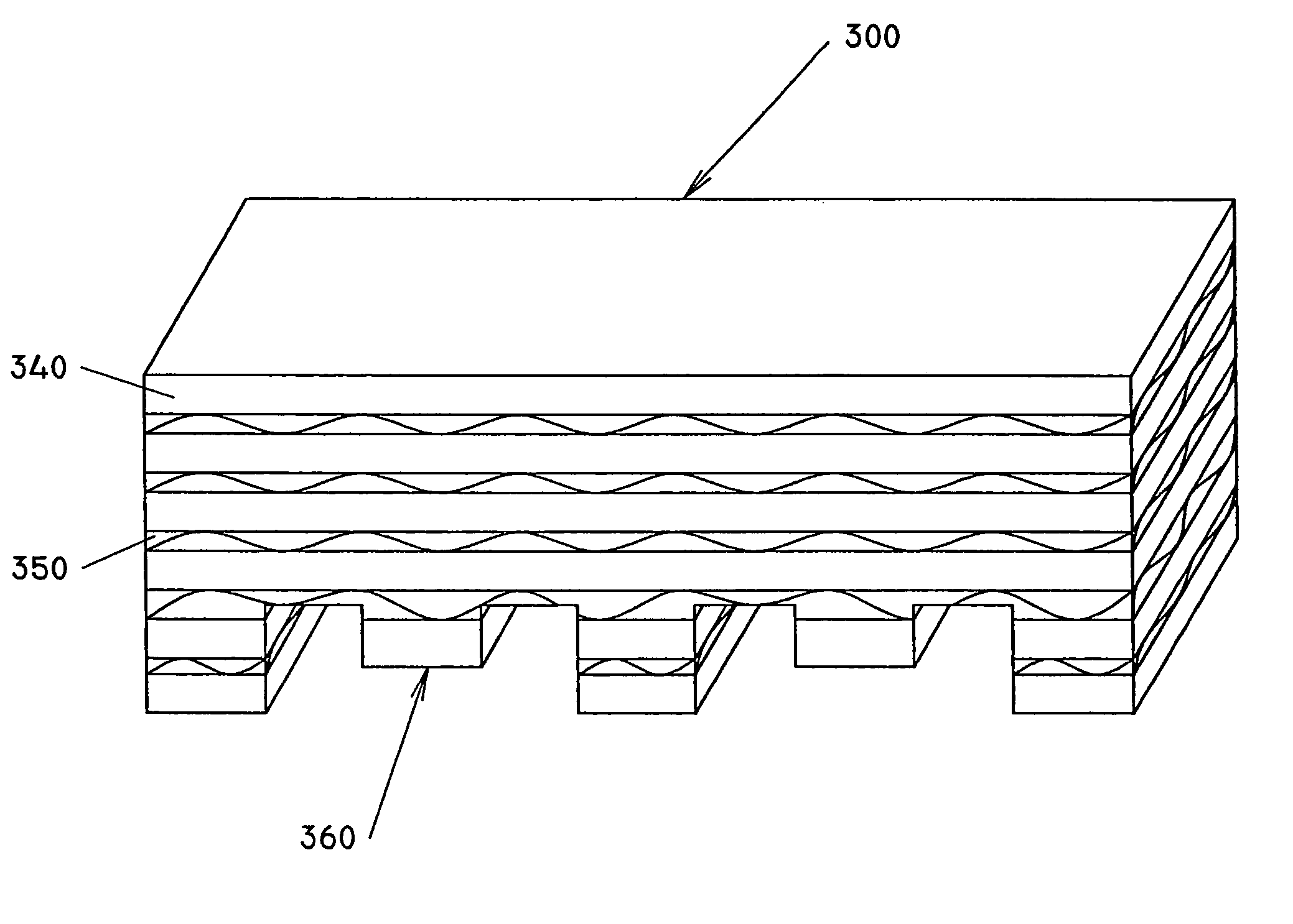
"The present invention is about a method for manufacturing a collimator for use in medical devices. The method involves generating a computer image of the collimator, sectioning it into smaller parts, and then forming the collimator by connecting the sections. The collimator is made with very precise dimensions and low tolerances. The invention can be used for manufacturing collimators for applications in devices other than medical devices. The method can be used with various techniques such as lithography or micro-machining. The collimator can be designed to have a variety of shapes and tolerances. The invention allows for the fabrication of collimators with high accuracy and low error tolerances."

Problems solved by technology

The combinations of any number of shapes can result in non-redundant design arrays (i.e. patterns in which not all shapes, sizes, and / or spacings are identical).

Method used


Image

  • Collimator fabrication
  • Collimator fabrication
  • Collimator fabrication

Examples


Embodiment Construction

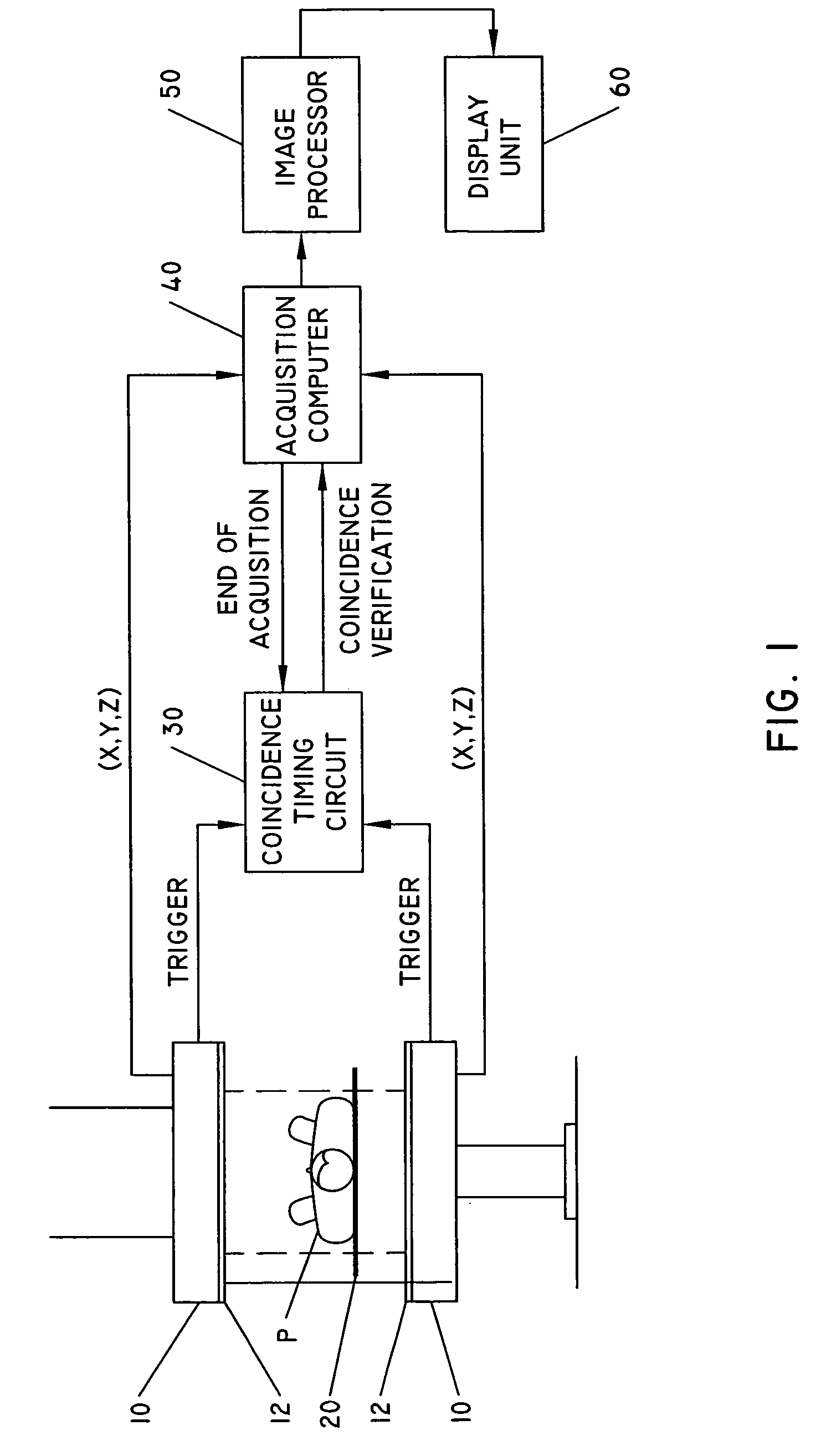
[0039] Referring now in greater detail to the drawings, wherein the showings are for the purpose of illustrating preferred embodiments of the invention only and not for the purpose of limiting the invention, FIG. 1 shows a block diagram of a prior art gamma ray detector system used for diagnostic purposes. A pair of gamma detectors 10, each optically coupled to a scintillation crystal 12, are disposed parallel to each other. Detector pair 10 is mounted on a gantry that can rotate about a patient P resting on a table 20. Additionally, either detector pair 10 or patient P can be transversely displaced in the direction perpendicular to the plane of the figure. This configuration allows for total body scanning and / or static imaging, both well-known techniques in NM coincidence measurements.

[0040] System hardware and software, schematically described in FIG. 1 by blocks 30, 40, 50 and 60, allows for coincidence measurements in accordance with technology well known in the art. Thus, no f...


PUM

PropertyMeasurementUnit
densityaaaaaaaaaa
thicknessaaaaaaaaaa
thicknessaaaaaaaaaa

Abstract

A collimator that formed from a plurality of metal foil layers that are shaped by use of lithographic techniques in specific shapes. The formed metal foil layers are stacked and aligned together and then connected together to form the collimator.

Description

[0001] This invention relates in general to grid-like structures of the type suitable for use as collimators. In particular, the invention relates to a method and an apparatus for forming collimator strips which can be assembled to form a collimator that can be used in imaging, diagnosing and / or treatment apparatuses that take images and / or effect treatment by use of gamma rays, electron beams, photon (X-ray) beams, or similar penetrating rays. BACKGROUND OF INVENTION [0002] Radiation emitting devices are generally known and used as imaging and as radiation therapy devices for the treatment of patients. [0003] Collimators are used in a wide variety of equipment in which it is desired to permit only beams of radiation emanating along a particular path to pass beyond a selected point or plane. Collimators are frequently used in radiation imagers to ensure that only radiation beams emanating along a direct path from the known radiation source strike the detector, thereby minimizing det...

Claims


Application Information

Patent Timeline
Patent Type & Authority Applications(United States)
IPC IPC(8): H01J5/18G21K1/00
CPCB22F2998/00G21K1/02G21K1/025G21K2201/00B22F3/008G01N23/201Y02P10/25B22F10/12G21F5/00G21K1/00
Inventor PINCHOT, JAMES M.
Owner JMP INDS
Learn More