
Method for reproduction of a compnent with a micro-joint and component produced by said method

a micro-joint and component technology, applied in the field of components production, can solve the problems of complex methods to define the surface of the joint, the possibility of functionalizing the components, and the difficulty of handling and positioning of micro-structured joints, and achieve the effect of reducing complexity and manufacturing costs

Inactive Publication Date: 2006-03-09
COMMISSARIAT A LENERGIE ATOMIQUE ET AUX ENERGIES ALTERNATIVES
View PDF3 Cites 37 Cited by
  • Summary
  • Abstract
  • Description
  • Claims
  • Application Information

AI Technical Summary

Benefits of technology

[0006] It is one object of the invention to remedy these drawbacks and, more particularly, to propose a method for production of micro-structured components minimizing the problems of biological compatibility, while reducing the complexity and manufacturing cost.

Problems solved by technology

However, handling and positioning of micro-structured joints is very difficult.
Techniques exist using in particular Polydimethylsiloxane as assembly joint, with complex methods to define the surface of the joint.
Other assembly techniques exist for substrates whose assembly surfaces may be locally very small, but these techniques require high temperatures or chemical preparations limiting the possibility of functionalizing the components to be assembled (for example by biological grafting) and are restrictive in the choice of materials.
In the field of polymer assembly, thermal welding also limits the choice of materials.
The use of pre-glued adhesive films presents the drawback of the presence of glue in contact with fluids to be handled and gives rise to problems of biological compatibility.
More conventional gluing techniques (glue distribution by syringe, pad printing, glue rollers, screen printing), apart from the problems related to polymerization of liquid glues in the presence of biological species, prove unsuitable for assembly of micro-structures presenting very small assembly surfaces (<20 μm).
Known assembly techniques thus give rise to problems of biological compatibility and / or are complex, which limits the application possibilities.
In addition, certain techniques do not enable reversible assembly of two components.

Method used


Image

  • Method for reproduction of a compnent with a micro-joint and component produced by said method
  • Method for reproduction of a compnent with a micro-joint and component produced by said method
  • Method for reproduction of a compnent with a micro-joint and component produced by said method

Examples


Embodiment Construction

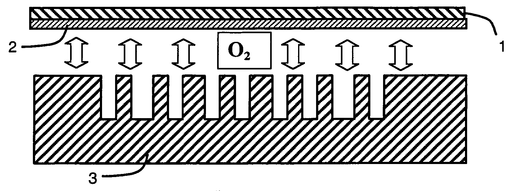
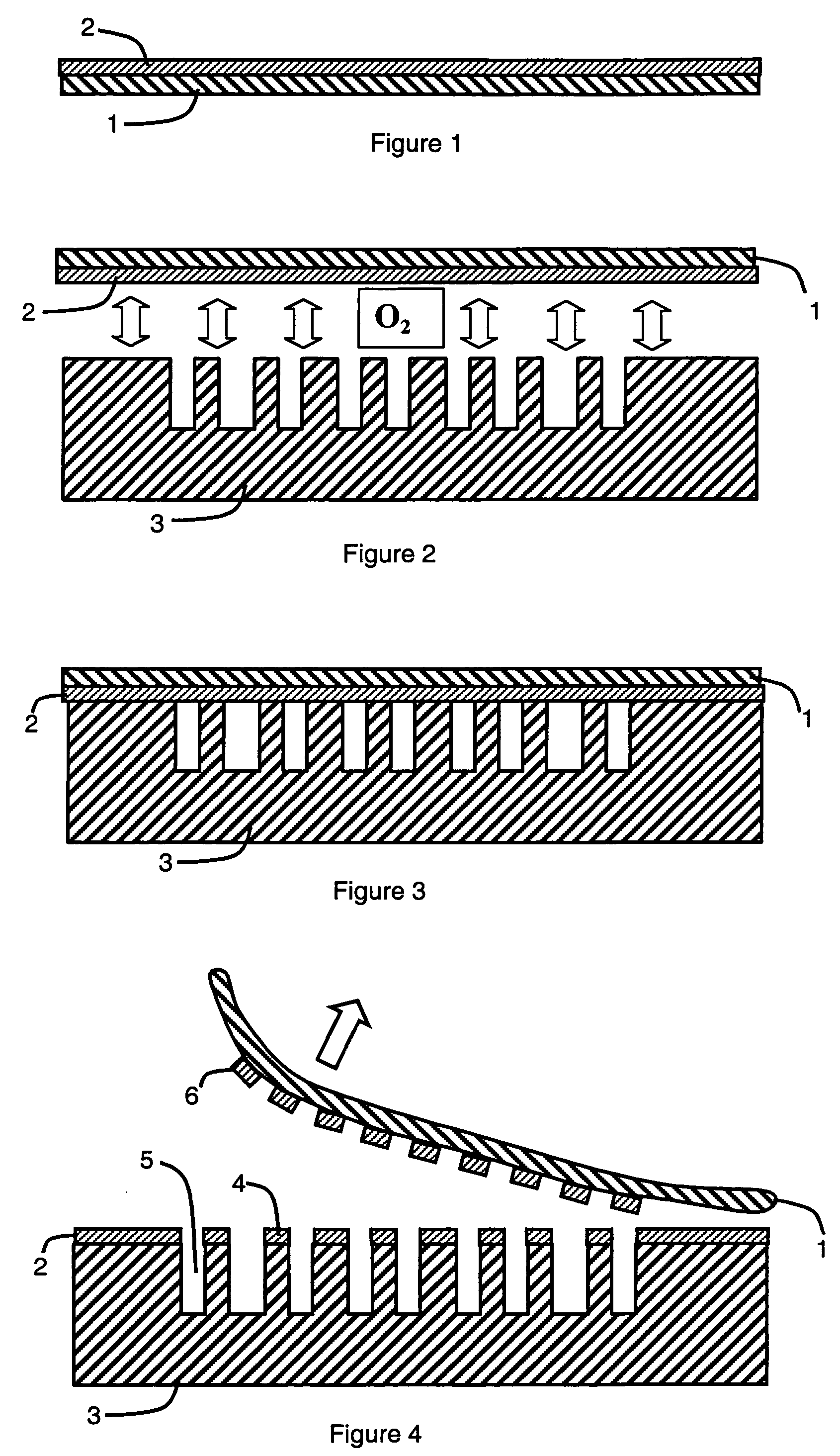
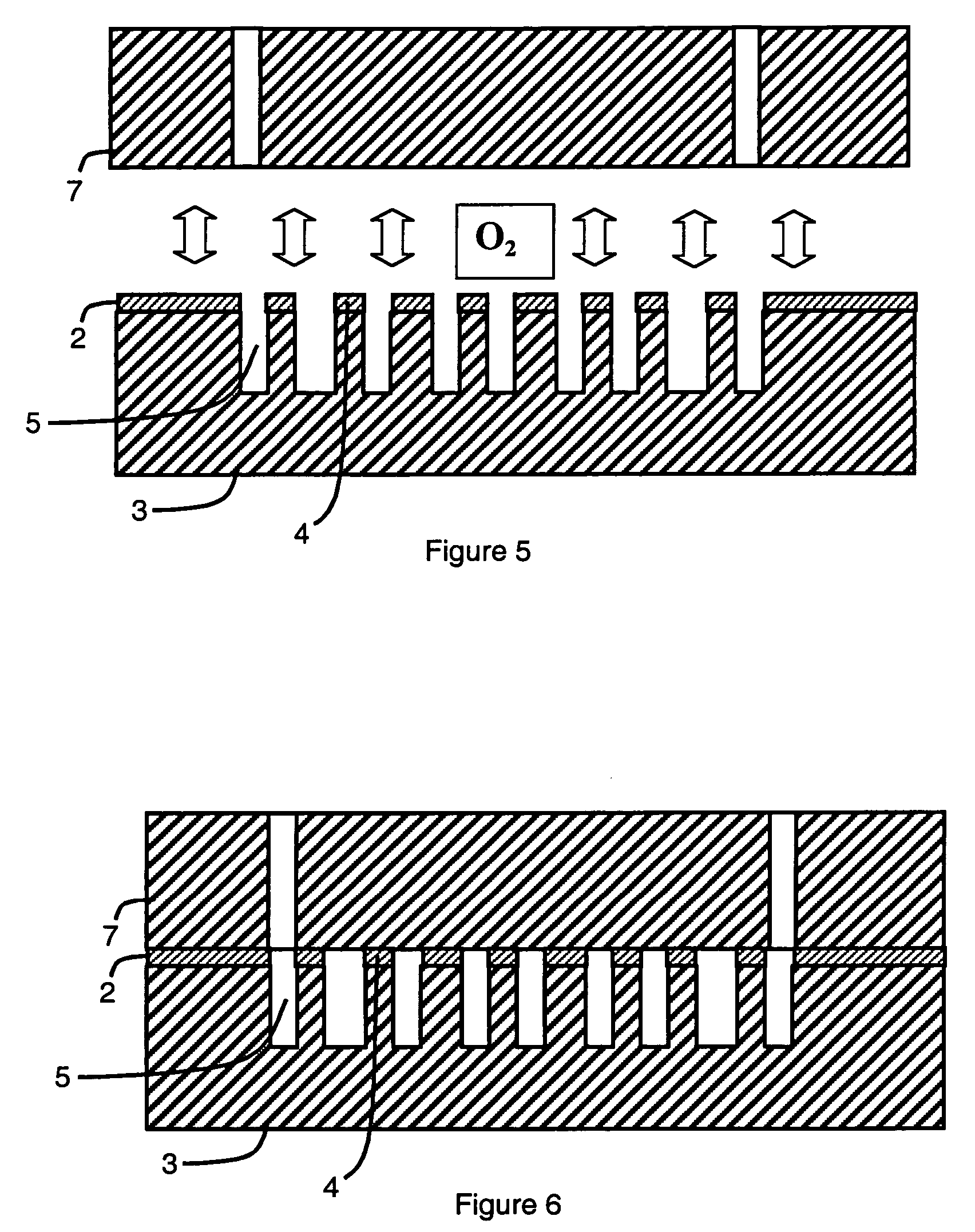
[0019] In a first step of the process represented in FIGS. 1 to 6, a thin layer of polymer 2 is deposited on a transfer substrate 1. A typically used deposition technique is spin coating. The polymer of the thin layer 2 and the material of the transfer substrate 1 must have a chemical affinity enabling the second and third steps described hereafter. In a preferred embodiment, the materials of the transfer substrate 1 and of the thin polymer layer 2 are both Polydimethylsiloxane (PDMS). One advantageous property of a PDMS transfer substrate 1 is its flexibility. Depending on the polymer used for the thin layer 2 and on the deposition technique, an additional intermediate cross-linking step, for example by heating, can be added just after deposition.

[0020] The second step (FIG. 3) consists in bringing the thin polymer layer 2, supported by the transfer substrate 1, into contact with the micro-structured substrate 3. The chemical affinity between the thin polymer layer 2 and the micro...


PUM

PropertyMeasurementUnit
Affinityaaaaaaaaaa

Abstract

The method for production of a component with a micro-joint comprises a first step of deposition of a layer of polymer designed to constitute an assembly joint on a transfer substrate, a second step of bringing the polymer layer into contact with a micro-structured substrate and a third step of removing the transfer substrate. Due to the difference of the chemical affinity between the polymer layer and the transfer substrate on the one hand and the chemical affinity between the polymer layer and the micro-structured substrate on the other hand, the zones of the polymer layer, which are in contact with the micro-structured substrate during the second step, remain on the micro-structured substrate after the third step. These zones constitute the assembly joint.

Description

BACKGROUND OF THE INVENTION [0001] The invention relates to a method for production of a component, comprising a micro-structured substrate and a complementary element assembled by means of an assembly joint. It also relates to a component produced by this method. STATE OF THE ART [0002] Production of micro-structured components, in particular micro-fluidic devices (biochips, lab-on-chip, etc.) or micro electro-mechanical devices (MEMS, MOEMS, etc.), generally involves surface or volume micro-structuring of at least one substrate where free spaces are created enabling fluids to circulate or to be stored. The cavities and channels thus created are open on at least one side and therefore have to be connected or assembled to another structure (open or closed cover, capillaries, other micro-fluidic substrate.). [0003] Assembly of micro-structured components requires assembly joints and seals that may be micro-structured. However, handling and positioning of micro-structured joints is ve...

Claims


Application Information

Patent Timeline
IPC IPC(8): B44C1/165B32B37/00B32B38/10B01J19/00B01L3/00B29C35/00B29C65/00B29C65/52B32B37/12B81B1/00B81C1/00
CPCB01J19/0093B29C66/5346B01J2219/00833B01J2219/0086B01L3/502707B01L2200/0689B01L2200/12B01L2300/044B01L2300/0819B29C35/00B29C65/526B29C66/024B29C66/54B29L2031/756B32B37/1284B81B2201/0214B81B2201/058B81C1/00119B81C1/00357B81C3/008B81C2201/019B81C2201/0191B01J2219/00783B29C66/0242B29C66/71B29C66/1122B29C66/112B29C66/131B29K2083/00
Inventor CONSTANTIN, OLIVIERMITTLER, FREDERIQUECOMBETTE, PHILIPPE
Owner COMMISSARIAT A LENERGIE ATOMIQUE ET AUX ENERGIES ALTERNATIVES
Learn More