
Mobile communication terminal

Inactive Publication Date: 2006-03-02
MITSUBISHI ELECTRIC CORP
View PDF5 Cites 35 Cited by
  • Summary
  • Abstract
  • Description
  • Claims
  • Application Information

AI Technical Summary

Benefits of technology

[0014] The present invention is made in order to solve the above-mentioned problems, and it is therefore an object of the present invention to provide a mobile communication terminal that can be operated with its wireless-communications function being disabled through a simple operation.

Problems solved by technology

A problem with prior art mobile communication terminals is that they cannot be made to operate in a state in which their wireless-communications functions are completely disabled after the power supply of the main body has been powered off.
Therefore, the mobile communication terminal cannot be assumed to be electronic equipment that enter “a state of not emitting any electric waves” under operating conditions, and there are cases where the user cannot use any other function of the mobile communication terminal other than the wireless-communications function while the user is staying in an airplane.

Method used


Image

  • Mobile communication terminal
  • Mobile communication terminal
  • Mobile communication terminal

Examples


embodiment 1

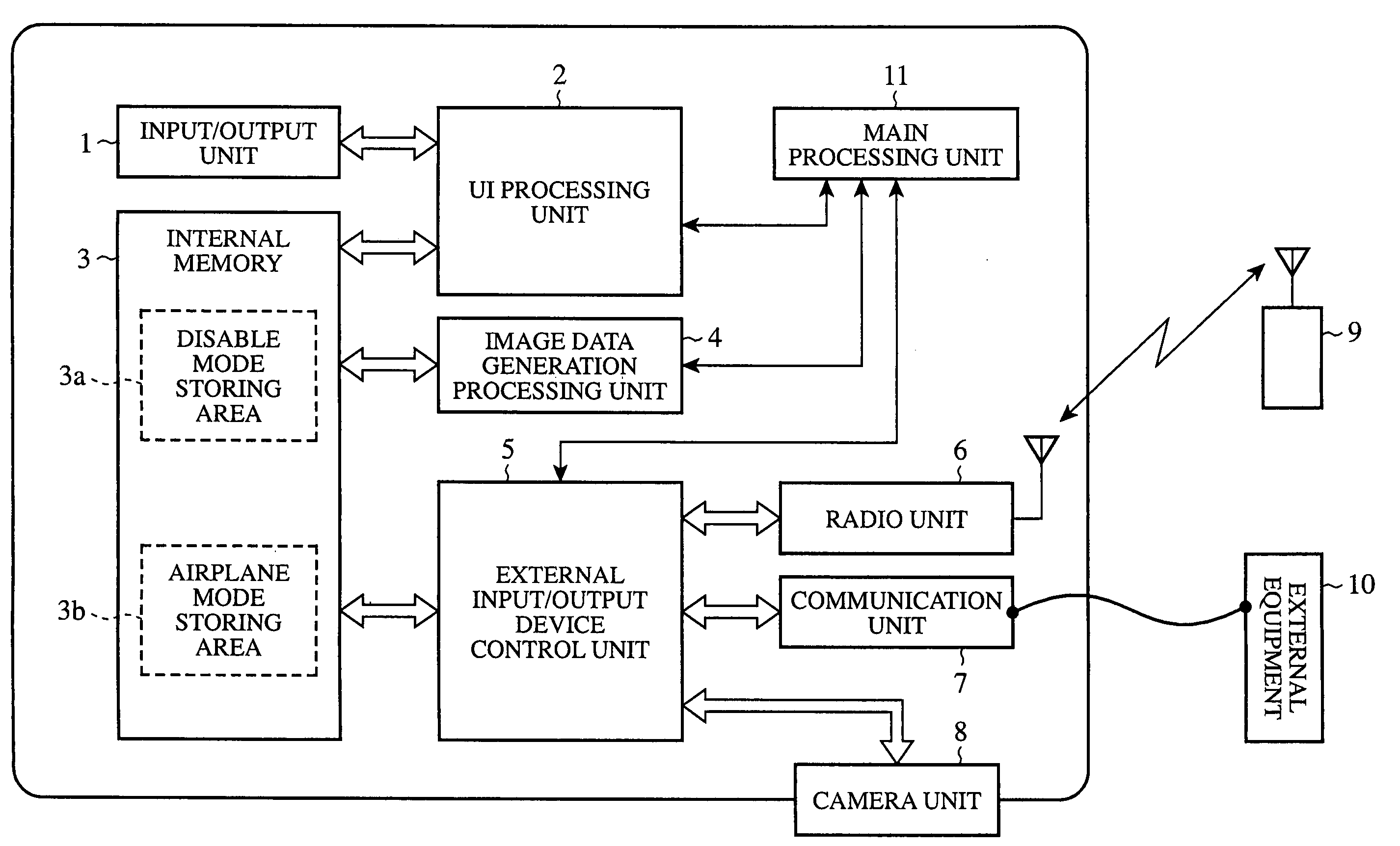
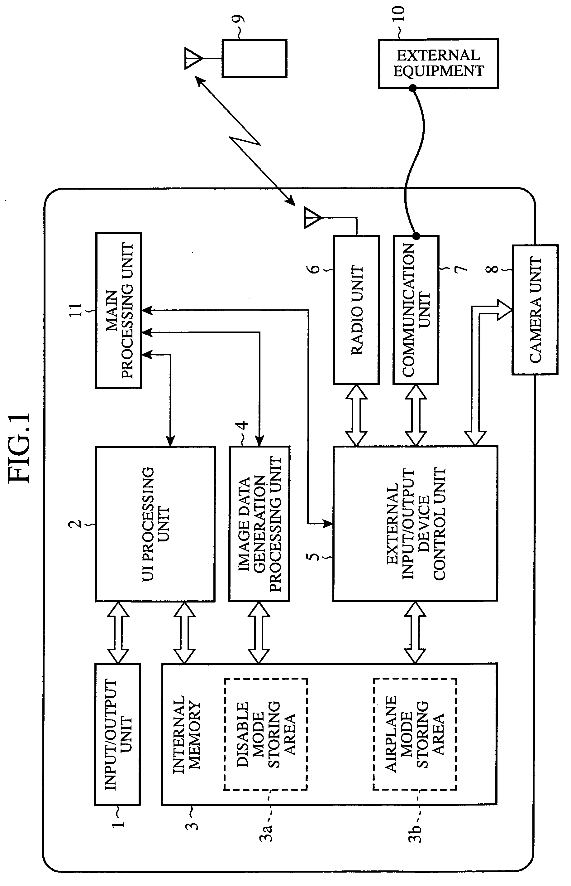
[0023]FIG. 1 is a diagram showing the structure of a mobile communication terminal in accordance with the present invention. This mobile communication terminal is provided with an input / output unit 1, a UI (User Interface) processing unit 2, an internal memory 3, an image data generation processing unit 4, an external input / output device control unit 5, a radio unit 6, a communication unit 7, and a main processing unit 11. The input / output unit (i.e., a setting input unit) 1 is a component which provides an interface between the mobile communication terminal and the user, and, is, for example, a set of key buttons, LCD, etc. which are standardly mounted on a mobile phone or PDA. The UI processing unit (i.e., a processing unit) 2 sets setting information about either a wireless-communications function disable mode in which a wireless-communications function of the radio unit 6 is disabled or an airplane mode to the internal memory 3 based on input information about mode setting from ...

embodiment 2

[0055] A mobile communication terminal according to this embodiment 2 has the same structure as that according to above-mentioned embodiment as shown in FIG. 1, and puts the wireless-communications function of a radio unit into a disable mode at the same time that the mobile communication terminal is made to switch on a power supply of a main body of the mobile communication terminal.

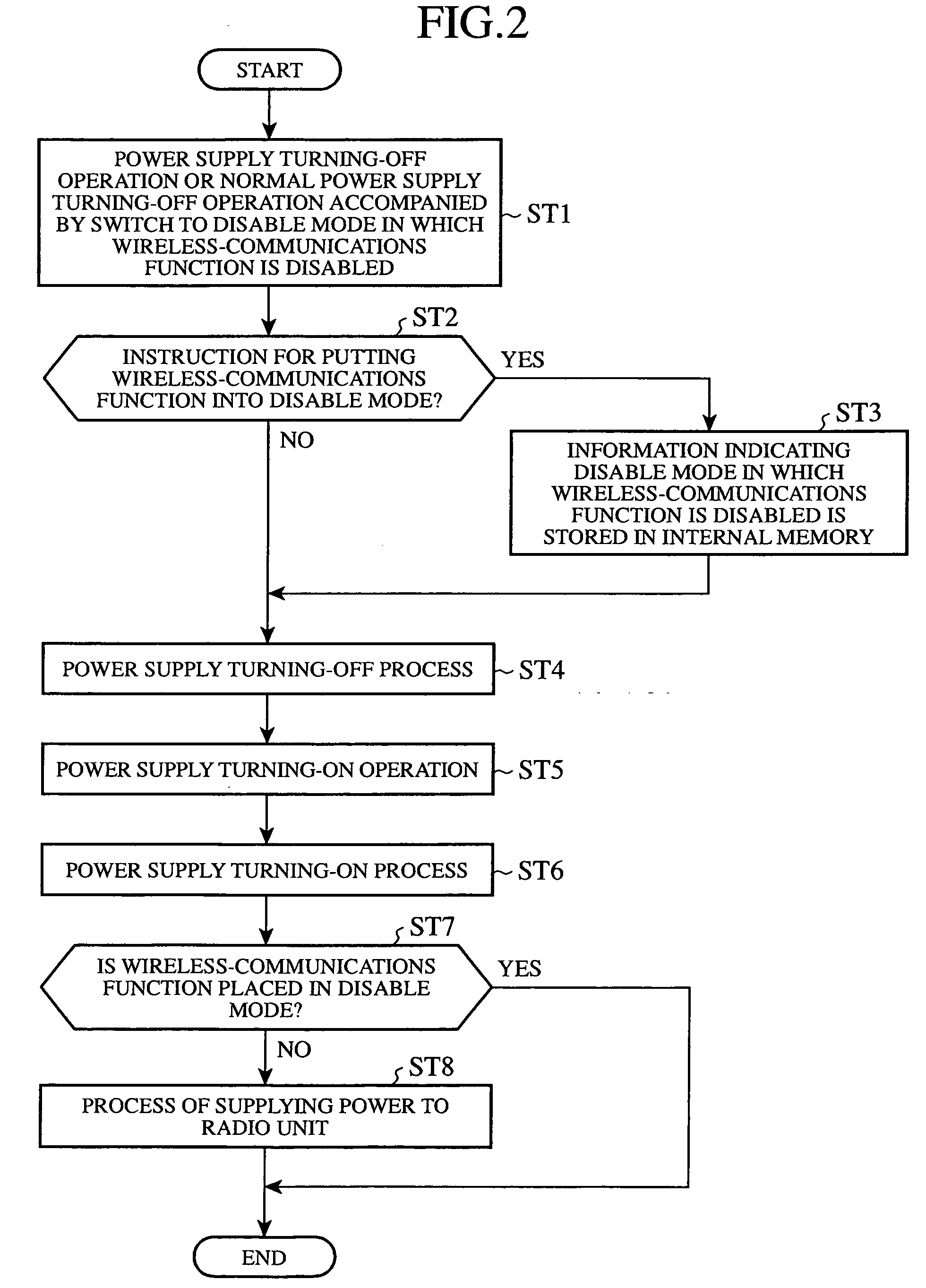
[0056] Next, the operation of the mobile communication terminal in accordance with embodiment 2 of the present invention will be explained. FIG. 3 is a flow chart showing the operation of the mobile communication terminal according to embodiment 2, and shows a process of disabling the wireless-communications function of the radio unit 6 at the same time the mobile communication terminal is made to switch on the main body of the mobile communication terminal.

[0057] First, a user pushes down a power supply key button of an input / output unit 1 in order to perform an operation of turning off the main body...

embodiment 3

[0069] A mobile communication terminal according to this embodiment 3 has the same structure as that of above-mentioned embodiment 1 shown in FIG. 1, and is so constructed as to, when a mode setting has been made, disable the wireless-communications function of a radio unit at the same time that it will be powered on even though the wireless-communications function has been enabled before the mobile communication terminal is powered off.

[0070] Next, the operation of the mobile communication terminal in accordance with embodiment 3 of the present invention will be explained. FIG. 4 is a flow chart showing the operation of the mobile communication terminal according to embodiment 3, and shows a process of starting the main body of the mobile communication terminal with the wireless-communications function being placed in a disable state in response to a user's normal turning-on operation of pushing down a power supply key button after the mobile communication terminal has been switch...


PUM


Abstract

A mobile communication terminal includes a radio unit (6) having a wireless-communications function, an input / output unit (1) for receiving disable setting information about a setting which disables the wireless-communications function of the radio unit (6), an internal memory (3) in which information indicating an operation mode of the radio unit (6) is stored, a UI processing unit (2) for storing information indicating a disable mode in which the wireless-communications function of the radio unit (6) is disabled in the internal memory (3) when the disable setting information is inputted to the input / output unit (1), and an external input / output device control unit (5) that controls power supply to the radio unit (6) when the mobile communication terminal is powered on, and that does not supply electric power to the radio unit (6) when the information indicating the disable mode is stored in the internal memory (3).

Description

BACKGROUND OF THE INVENTION [0001] 1. Field of the Invention [0002] The present invention relates to a mobile communication terminal that can enable or disable its wireless-communications function when the mobile communication terminal is started. [0003] 2. Description of Related Art [0004] According to the Aviation Act of Japan, it is stipulated that users must not always effect the operation of mobile phones and other electronic equipment that enter “a state of emitting electric waves” under operating conditions while users must not effect the operation of mobile phones and other electronic equipment that enter “a state of not emitting any electric waves” under operating conditions only during takeoff or landing. [0005] There have been provided prior art technologies which are disclosed in the following patent references 1 to 3 to the requests of the Aviation Act of Japan. In accordance with the prior art technology disclosed in patent reference 1, a detection mechanism for detect...

Claims


Application Information

Patent Timeline
IPC IPC(8): H04Q7/20H04M1/72463H04W88/02
CPCH04W88/02H04M1/72577H04M1/72463
Inventor HORI, TOSHIRODOI, SEIJIRO
Owner MITSUBISHI ELECTRIC CORP
Learn More