
Packaging system having loading carousel

Active Publication Date: 2006-03-02
GRAPHIC PACKAGING INT
View PDF45 Cites 43 Cited by
  • Summary
  • Abstract
  • Description
  • Claims
  • Application Information

AI Technical Summary

Benefits of technology

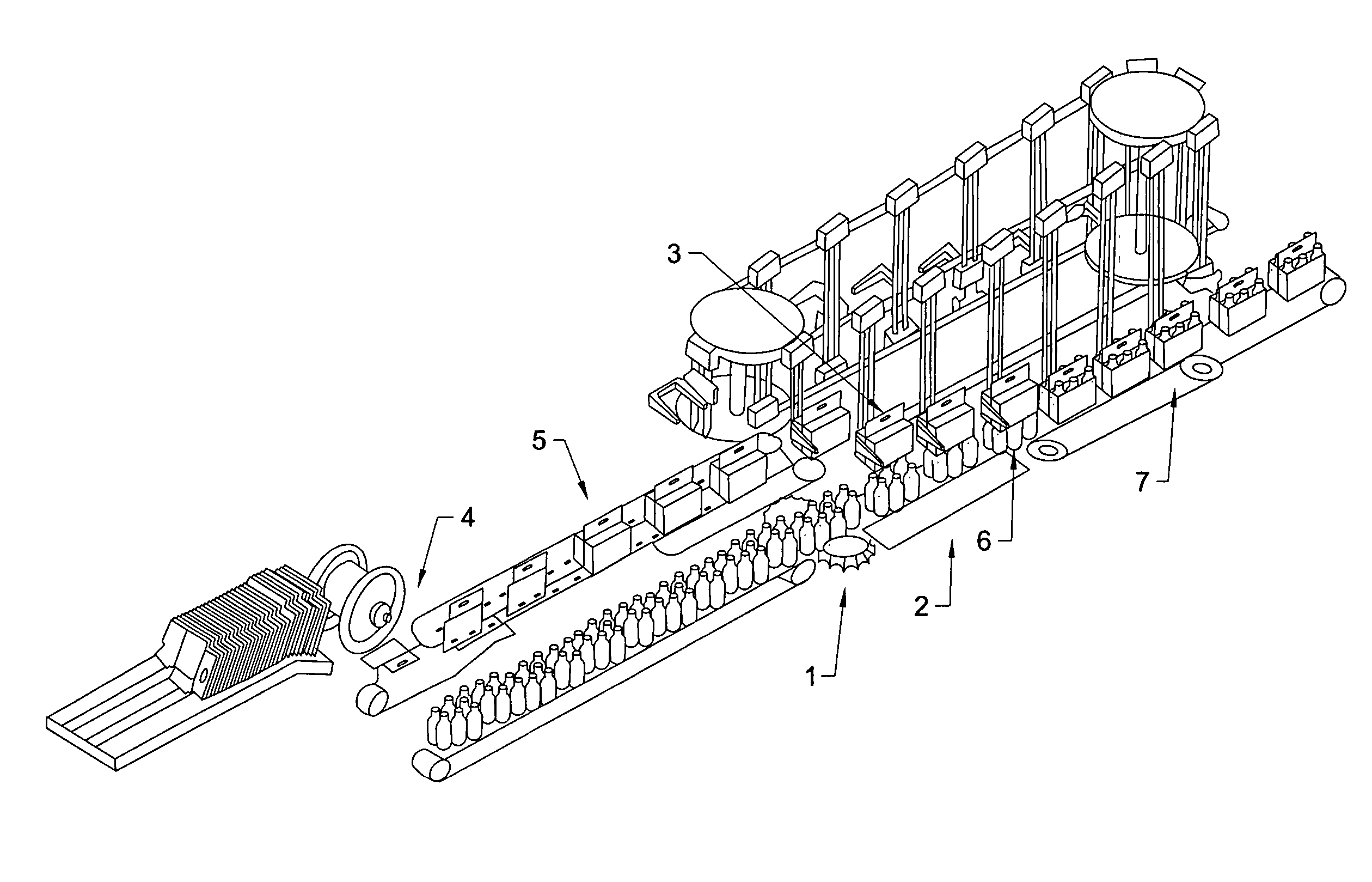
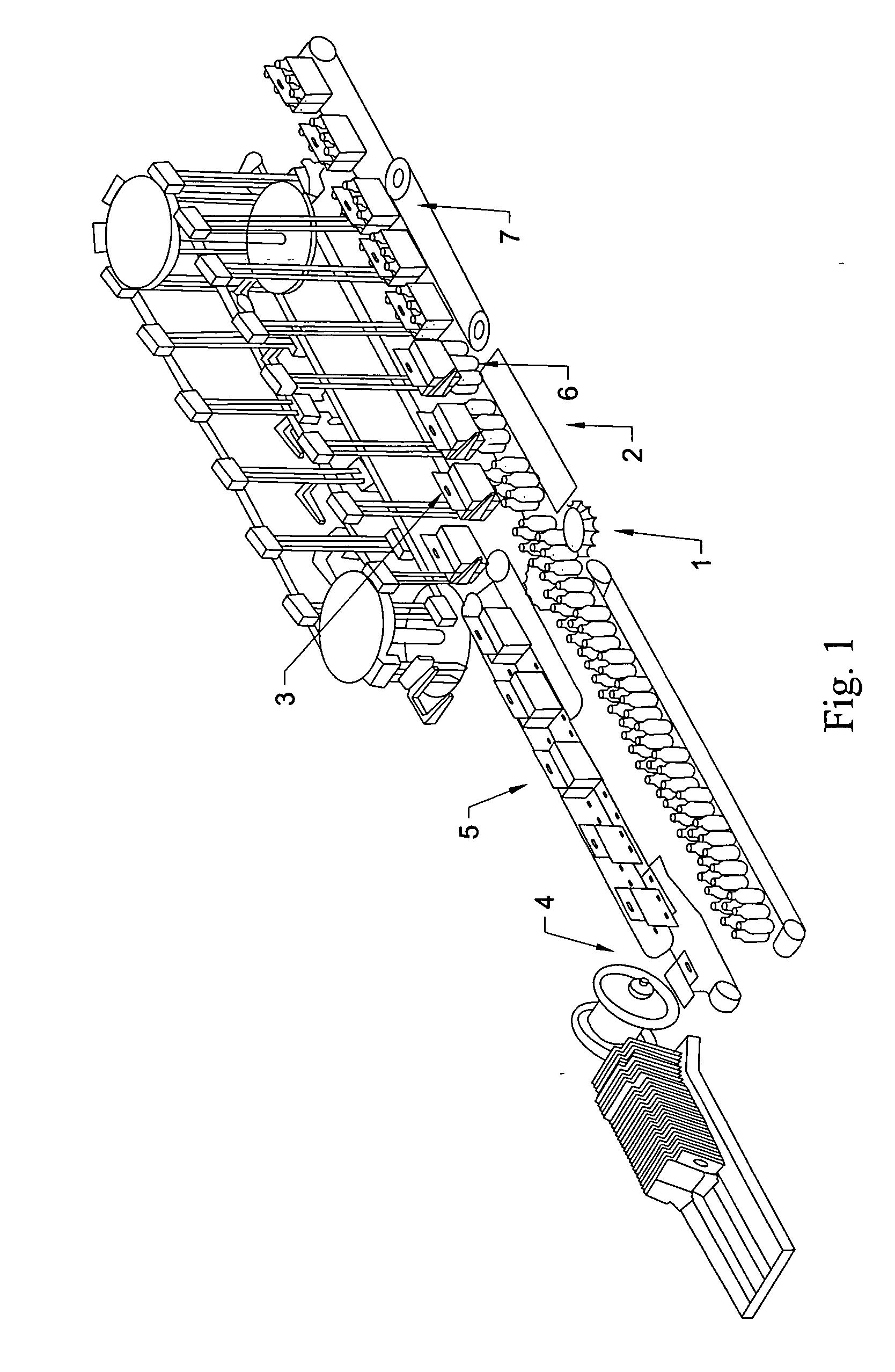
[0011] According to one aspect of the present invention, use of two sides of the loading carousel allows the packaging system to open and load cartons with groups of articles in a significantly reduced length, space, and / or footprint, without reducing packaging speed. Also, because the pickup stroke can occur on one side of the carousel, and the loading stroke can occur on the opposite side, the loading carousel can be significantly shorter in height than conventional carousels. In addition, the relatively small size of the loading carousel reduces the mass of moving parts in the carousel, meaning a smaller inertia during operation.

Problems solved by technology

However, plant space often is at a premium and it is not always possible to extend machinery to an optimal size.
Even in cases where the linear extent of the packaging machine is not limited, a large loading carousel necessarily has a large mass of moving parts, which entails a correspondingly large inertia during operation.
Drive mechanisms must therefore be larger, and high speed operation of the larger machine may result in higher maintenance costs, higher rates of failure, and other manufacturing problems.

Method used


Image

  • Packaging system having loading carousel
  • Packaging system having loading carousel
  • Packaging system having loading carousel

Examples


Embodiment Construction

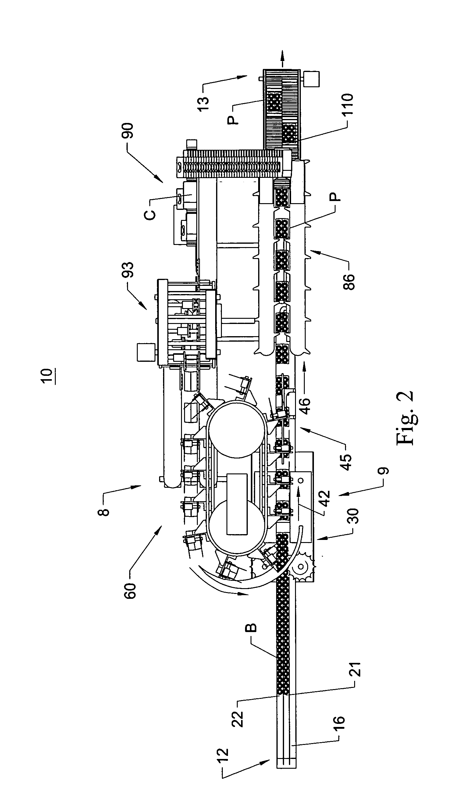
[0021]FIGS. 2-7 illustrate a high speed packaging system 10 according to an embodiment of the present invention. The packaging system 10 generally is designed to provide a substantially continuous motion system for high speed packaging of various types of articles in a variety of configurations of containers, including, for example, six-pack, four-pack, or eight-pack cartons, as well as smaller or larger configurations. For the purposes of illustration and simplicity of description, the packaging system embodiment discussed in detail below is described as loading bottles B into cartons C to form packages P.

[0022] Referring to FIG. 2, the packaging system 10 has a first, upstream or inlet end 12 and a second, downstream or outlet end 13. The packaging system 10 comprises the following general components: a carton infeed system 90 having an opener 93 for providing opened cartons C in the system 10, a loading carousel 60 for loading bottles B in the cartons C, an article transport or ...


PUM

PropertyMeasurementUnit
Lengthaaaaaaaaaa

Abstract

A packaging system utilizes two sides of a loading carousel, which reduces both the height and footprint of the packaging system. Mass and inertia are also reduced, allowing higher operational speeds. The loading carousel receives opened cartons on a first side and lowers them over product groups on a second side.

Description

TECHNICAL FIELD [0001] The present invention relates generally to a high speed packaging machine having a loading carousel. BACKGROUND [0002] The packaging of articles such as bottles, cans, and other similar articles in cartons or other containers is a highly automated process, with conventional automated packaging equipment generally being run at high packaging speeds in order to maximize output. In a typical packaging machine for packaging articles such as bottles, cans and the like, articles to be packaged are fed into the packaging machine in a line or series of lines along an infeed conveyor, after which the articles are grouped together in various standard configurations or groupings, such as four, six, eight, twelve, or twenty-four pack configurations. The groups of articles are then packaged into a box, a carton, or other type of container. The placement of the articles within a container can be done in a variety of ways, depending upon the type of package in which the arti...

Claims


Application Information

Patent Timeline
IPC IPC(8): B65B21/24
CPCB65B5/024B65B21/06B65B21/22B65B65/003B65B43/30B65B43/50B65B21/242
Inventor FORD, COLIN P.
Owner GRAPHIC PACKAGING INT
Learn More