Gas purifying apparatus, image forming apparatus having the same, and method of purifying gas of the image forming apparatus

Inactive Publication Date: 2006-02-23
S PRINTING SOLUTION CO LTD
View PDF2 Cites 19 Cited by
  • Summary
  • Abstract
  • Description
  • Claims
  • Application Information

AI Technical Summary

Benefits of technology

[0022] Accordingly, the present invention solves the above-mentioned problems. One aspect of the present invention is to provide a gas purifying apparatus having an ozone generation unit which can minimize the volume of catalyst otherwise required for oxidatively decomposing impurities such as flammable hydrocarbons contained in gases generated at the time of fixing an image. The invention is also directed to an apparatus to improve a gas purifying rate, an image forming apparatus having such a gas purifying apparatus, and a method of purifying the gas.
[0023] Another aspect of the present invention is to provide a gas purifying apparatus having an ozone generation unit which can control the amount of ozone generated in such a manner that the amount can be varied according to the amount of impurities such as flammable hydrocarbon gas contained in the gas generated by fixing an image. Controlling the amount of ozone produced enables control of the purifying rate of the impurities contained in the gas so the rate of purification can be increased and decreased as needed.
[0027] Preferably, the catalytic unit comprises a carrier containing gamma alumina and / or diatomaceous earth, and a catalyst coated on the outer surface of the carrier and selected from the group consisting of Pd, Pt, Co3O4, PdO, Cr2O3, Mn2O3, CuO, SeO2, FeO2, Fe2O3, V2O5, NiO, Ag, MoO3 and TiO2. The catalyst is present in an amount sufficient to decompose the impurities in the gas catalytically. The carrier preferably has a plurality of openings formed in the air flow direction and shaped to have a cross-sectional shape selected from a grid shape, a corrugated cardboard shape and a honeycomb shape, so that the area to be contacted with hydrocarbon gas can be increased. The openings in the catalytic unit have openings to provide a surface area that is sufficient to decompose the impurities and particularly the hydrocarbon by-products in the exhaust gas produced during the heating and fixing process of the toner image.
[0034] The catalytic unit may comprise a carrier containing one component selected from the group consisting of gamma alumina and diatomaceous earth, and a catalyst coated on the outer surface of the carrier and formed from at least one component selected from a group consisting of Pd, Pt, Co3O4, PdO, Cr2O3, Mn2O3, CuO, SeO2, FeO2, Fe2O3, V2O5, V2O5, NiO, Ag, MoO3 and TiO2. The carrier preferably has plural openings formed in the air flow direction and shaped to have a cross-sectional shape selected from a grid shape, a corrugated cardboard shape and a honeycomb shape, so that the area to be contacted with hydrocarbon gas can be increased.

Problems solved by technology

The flammable hydrocarbon gases are volatile organic compound (VOC) so that gas not only pollutes the surrounding environment but also emits an unpleasant smell when released from the printer.
However, the gas purifying apparatus 10 configured as described above has a disadvantage in that it is necessary to frequently replace the filtering device 12 with new one.
In addition, because the gas purifying apparatus 10 directly discharges hot air out of the printer after the hot air has passed the filtering unit 12, it can cause a safety problem that a user may get a burn.
However, the gas purifying apparatus 10′ has a problem in that the manufacturing costs are high and the apparatus is difficult to manufacture, because the cooling fan 32 and the coil tube 31 are employed to cool hot air in addition to the ventilation fan 40.
The construction of the apparatus of FIG. 2 is very complicated.
Furthermore, the purifying apparatus 10′ also has a problem in that the manufacturing and maintenance costs are high because it is necessary to employ an expensive heater 21 having a high heating temperature in the range of about 1000-1300° C. so as to pyrolyze hydrocarbon gas into carbon dioxide and vapor.
However, the gas purifying apparatus 10″ still has problems of high manufacturing costs and complicated construction due to the addition of the cooling fan 32 and the coil tube 31 of the heat exchange unit 30.
Moreover, the gas purifying apparatus 10″ also has the disadvantage of using an expensive platinum catalyst 22 for promoting the oxidative decomposition of hydrocarbon.

Method used


Image

  • Gas purifying apparatus, image forming apparatus having the same, and method of purifying gas of the image forming apparatus
  • Gas purifying apparatus, image forming apparatus having the same, and method of purifying gas of the image forming apparatus
  • Gas purifying apparatus, image forming apparatus having the same, and method of purifying gas of the image forming apparatus

Examples


example 1

[0057]FIGS. 4 and 5 show a gas purifying apparatus 150 according to a first preferred embodiment of the present invention.

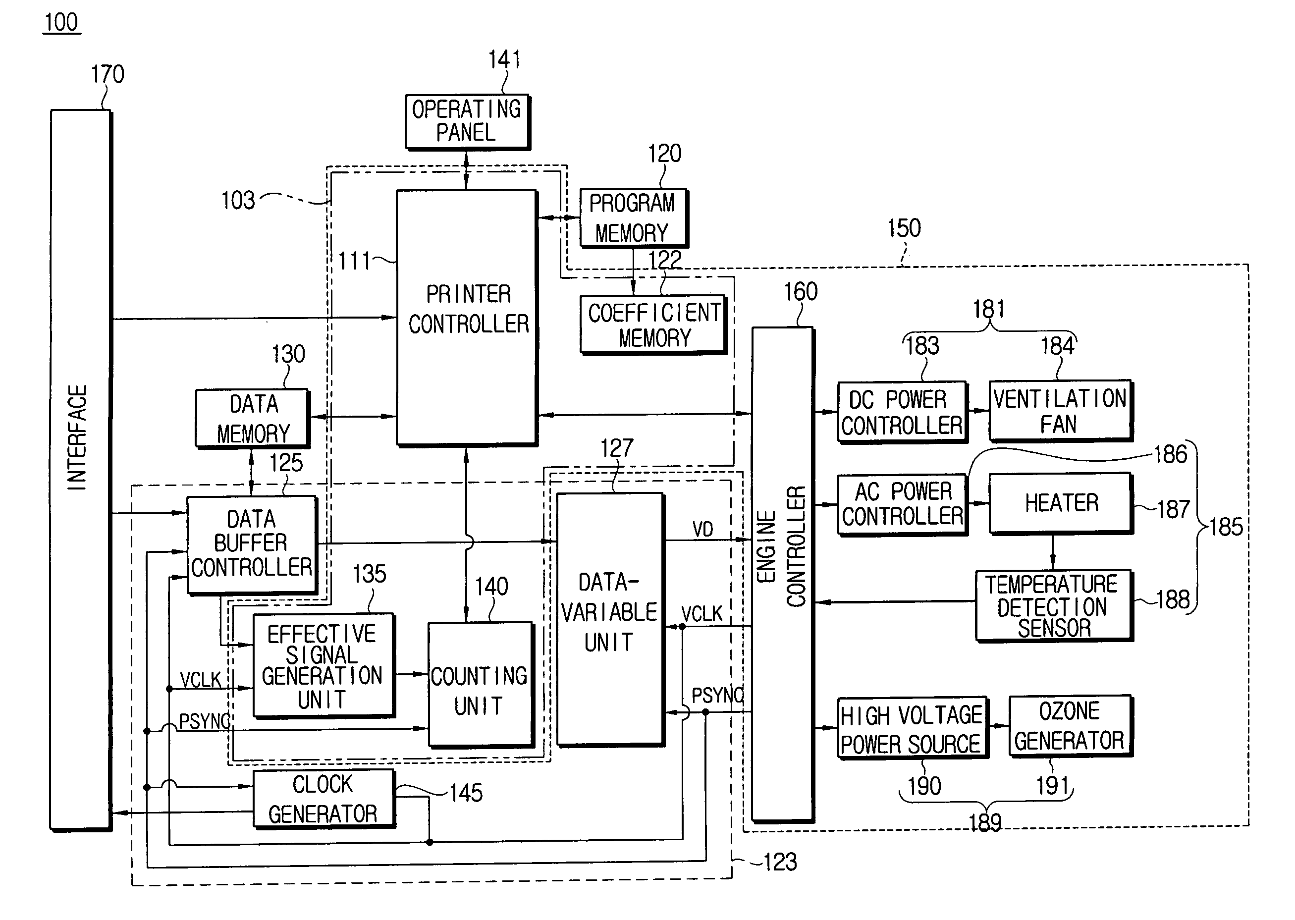
[0058] An image forming apparatus, to which the gas purifying apparatus 150 may be applied, is a wet electrophotographic color printer 100 which internally processes data transmitted from a computer (not shown) or the like through an interface 170 and executes a print mode.

[0059] The wet electrophotographic color printer 100 comprises an interface 170 forming a connection part for interchanging data with a computer or the like, an operating panel 141 for inputting a user's command or selection, a program memory 120 for storing various control programs required for driving the printer 100, a data memory 130 for storing various data generated as the control programs are implemented and print data transmitted through the interface 170, a printer controller 111 for implementing the control programs to control respective parts of the printer, a engine controller 160...

example 2

[0113]FIGS. 11 and 12 show an image forming apparatus 150′ having a gas purifying apparatus 150′ according to a second preferred embodiment of the present invention.

[0114] The image forming apparatus having the gas purifying apparatus 150′ of the second embodiment of the present invention is a wet electrophotographic color printer 100′, which internally processes data transmitted through an interface 170 from a computer (not shown) or the like as in the first embodiment.

[0115] As shown in FIG. 11, the wet electrophotographic color printer 100′ comprises an interface 170 forming a connection part for interchanging data with a computer or the like, a program memory 120 for storing various control programs required for driving the printer 100, a data memory 130 for storing various data generated as the control programs are implemented and print data transmitted through the interface 170. A printer controller 111 is provided for implementing the control programs to control respective ...


PUM

PropertyMeasurementUnit
Fractionaaaaaaaaaa
Fractionaaaaaaaaaa
Fractionaaaaaaaaaa

Abstract

A gas purifying apparatus oxidatively decomposes and discharges impurities such as flammable hydrocarbons (CmH2n) contained in gas generated from a toner by fixing an image. An image forming apparatus having a gas purifying apparatus, and a method of purifying gas of the image forming apparatus are also provided. The gas purifying apparatus comprises a fan unit for ventilating air, a heating unit for heating the air ventilated by the fan unit, a catalytic unit for facilitating oxidative decomposition of impurities contained in the air, and an ozone generation unit located upstream of the heating unit and the catalytic unit in the air flow direction. By providing the ozone generation unit for facilitating the oxidative decomposition reaction by the catalytic unit for impurities contained in gas generated by fixing an image, the gas purifying rate can be improved and by minimizing the reaction area of catalyst oxidizing impurities, and reducing the manufacturing costs.

Description

CROSS-REFERENCE TO RELATED APPLICATIONS [0001] This application claims the benefit of Korean Patent Application Nos. 2004-66550 filed on Aug. 23, 2004; and 2004-66843 filed on Aug. 24, 2004, in the Korean Intellectual Property Office, the disclosures of which are incorporated herein by reference in their entirety. BACKGROUND OF THE INVENTION [0002] 1. Field of the Invention [0003] The present invention relates to an image forming apparatus, such as a wet electrophotographic printer. In particular, the present invention relates to a gas purifying apparatus for oxidatively decomposing and discharging impurities, such as flammable hydrocarbon (CmH2n) gases or vapors, contained in a gas generated at the time a transferred toner image is fixed onto a paper. The invention is also directed to an image forming apparatus having a gas purifying apparatus, and to a method of purifying gases produced during the fixing of the toner image to a substrate. [0004] 2. Description of the Related Art [...

Claims


Application Information

Patent Timeline
IPC IPC(8): B01J19/08
CPCB01D53/8668B01D2251/104B01J19/2485B01J19/32C01B13/11B01J2219/00135B01J2219/32466B41J29/17B41J29/377B01J2219/0004
Inventor SEORL, KWOANG-JOEKIM, HYOU-JIN
Owner S PRINTING SOLUTION CO LTD
Why Eureka
Try Eureka