Reinforced pad and method of making

Inactive Publication Date: 2007-02-13
CONTOUR FABTORS
View PDF15 Cites 4 Cited by
  • Summary
  • Abstract
  • Description
  • Claims
  • Application Information

AI Technical Summary

Benefits of technology

[0008]In those instances in which the pad has an other-than-planar shape or where the required manufacturing volume and complexity are such that fabrication is economically preferable to molding, it may be desirable, for least material costs, least tooling costs, or greatest ease of production, to fabricate the pad in a modified shape deformed toward planarity. This deformation serves to decrease the effective enveloping volume of the pad and minimize material usage and / or tooling volume and complexity, and / or serves to make the required shapes easier to fabricate by means of conversion of complex-curved surfaces into single-curved or planar surfaces. Techniques herein described are then used to cause the pad to attain its desired final shape and properties. The selective combination of the isotropic body properties and anisotropic reinforcing sheet cause the pad to have the desired anisotropic properties.
[0009]In one embodiment of a pad that is planar or single-curved and has length and width dimensions significantly greater than its thickness dimension, the foam portion of the pad body is made in halves of the desired length and width and divided on the thickness dimension, or molded into such final shape halves. In either of these two cases a reinforcing sheet then is inserted between and bonded to the two halves by means of an adhesive or other effective means, together with elastic deformation of the body halves and reinforcing sheet as required so that the resulting assembly has the desired final shape, dimensions, and other mechanical properties. Alternatively, the body may be molded around a pre-placed reinforcing sheet. This embodiment can provide the desired property of greater compression and extension stiffness along the length and width axes than along the thickness axis.
[0010]In another embodiment a pad that is to have a single-curved final shape, but for economic reasons must be fabricated from least-cost materials, the body halves are fabricated as flat shapes from economical roll-type foam material. The body halves and the reinforcing sheet then may be assembled and bonded in a suitable curved jig or fixture, with each piece suitably elastically deformed to follow the curvature of the fixture and the other pieces with which it is to be combined. The curvatures of the fixture may be different from, and typically smaller-radiused than, those of the desired final shape so that, when the assembled pad is removed from the fixture, it will assume the desired final shape. In this embodiment the inherent restorative elastic force of the individual deformed pieces is less than the overall effective bending stiffness of the bonding assembly, so the desired curved shape is retained. This embodiment can provide the desirable property of greater compressive stiffness along the length and width axes than along the thickness axis, and also allows achievement of a non-polar final shape even though it is made of inexpensive planar materials.
[0012]If the pad of the embodiments referred to above is to be coated to provide a protective, washable outer skin, and if the coating material is one which shrinks as it dries or cures, the reinforcing sheet typically is located on the pad's neutral bending axis in such manner as to maintain a balance in the shrink forces generated by the drying or curing of the coating so as to avoid warping due to unbalanced forces.

Problems solved by technology

It is the nature of such liquid coatings that, even when applied to a pad with great care, the shrinkage and corresponding compression are variable and unpredictable, thereby resulting in the production of a pad whose dimensions are not acceptable.
However, the means by which dimensional stabilization is achieved should not unduly stiffen the pad in the thickness dimension and thereby prevent the pad from providing comfortable support for a person.
The shape of a positioning pad therefore may be geometrically complex.
The most commonly used means for shaping such pads includes costly equipment or tooling which causes the cost of such pads to be inordinately expensive if the expense of the required shaping equipment or tooling must be amortized over a small production volume.

Method used


Image

  • Reinforced pad and method of making
  • Reinforced pad and method of making
  • Reinforced pad and method of making

Examples


Embodiment Construction

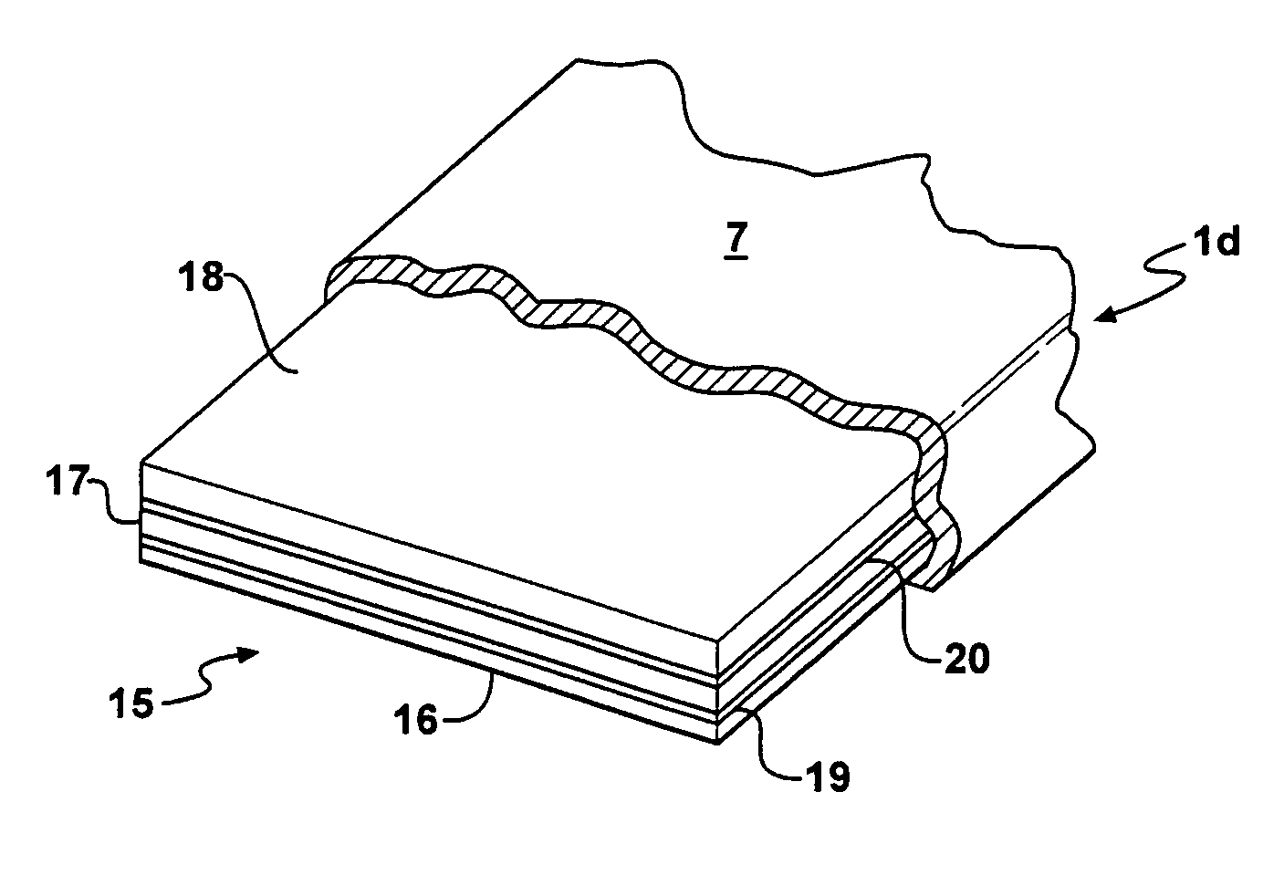
[0028]A cushioning pad constructed in accordance with the embodiment disclosed in FIGS. 1 and 2 is designated generally by the reference character 1 and comprises a composite body 2 formed of two correspondingly shaped foam layers 3 and 4 between which is sandwiched a reinforcing sheet 5 having a configuration, in plan, corresponding to that of the layers 3 and 4, but being substantially thinner than each of the latter.

[0029]Each of the layers 3 and 4 has substantially uniform isotropic mechanical properties and may be formed from polymeric foam material such as urethane, olefin, vinyl nitrile, rubber, or other similar material which is readily deformable in its length, width, and thickness axes or dimensions and is elastically recoverable from a deformed condition upon removal of the deforming force. The compressive stiffness and other mechanical properties of the material forming the layers are variable, as is well known, but if the finished pad is to support or position a human, ...


PUM

PropertyMeasurementUnit
Lengthaaaaaaaaaa
Thicknessaaaaaaaaaa
Widthaaaaaaaaaa

Abstract

A cushioning and positioning pad has a body formed from superposed layers of resiliently compressible foam material and a reinforcing sheet embedded between adjacent layers. The reinforcing sheet is of such stiffness as to resist contraction along its length and width dimensions, but is resiliently bendable in response to the application of a force along its thickness dimension. The reinforcing sheet resists undesirable contraction lengthwise and widthwise of the pad when the latter is encapsulated in a curable coating of material which shrinks as it cures.

Description

RELATED APPLICATION[0001]This application is a continuation of application Ser. No. 09 / 628,466 filed Jul. 31, 2000 now abandoned.[0002]This invention relates to a reinforced cushioning or positioning pad composed of elastomeric polymeric foam material having substantially isotropic properties and a reinforcing insert formed of material having anisotropic properties embedded in the pad.BACKGROUND OF THE INVENTION[0003]In some instances a cushion or pad is used to provide comfortable support for a person who is undergoing a medical procedure which may include imaging. Such a pad typically is generally planar and made from polymeric foam material of substantially uniform thickness. The length and width of such a pad normally are much greater than its thickness. Such a pad often is provided with an outer, skin-like protective coating formed by the application to the exterior of the pad of one or more coats of liquid paint-like material which then is permitted to dry or cure. Typically, ...

Claims


Application Information

Patent Timeline
IPC IPC(8): B32B3/06C08F2/46A61G7/057A61G13/10B29C44/06B32B5/18B32B37/12B32B38/18
CPCB29C44/06B32B5/18A61G7/05715A61G13/10B32B37/12Y10T428/239B32B2305/022B32B2305/08Y10T428/24273Y10T428/233B32B38/1866Y10T428/249981Y10T428/249978Y10T428/249992Y10T428/249991Y10T428/249987
Inventor SCHAEFER, JOHN W.
Owner CONTOUR FABTORS
Why Eureka
Try Eureka