
Wireless communication system, control station, and terminal station

a technology of communication system and terminal station, applied in the direction of electrical equipment, network topologies, connection management, etc., can solve the problem of not being able to establish a direct link (dl) for some applications

Inactive Publication Date: 2006-02-16
PIONEER CORP
View PDF5 Cites 11 Cited by
  • Summary
  • Abstract
  • Description
  • Claims
  • Application Information

AI Technical Summary

Benefits of technology

[0018] A direct link (DL) protocol is proposed in the new IEEE 802.11e standard whereby communication with the control station AP300 is also possible, and whereby direct communication can be performed between the terminal stations STA401 and 402. In a normal transmission in which a direct link is not established, a packet is first transferred from the terminal station STA#1 to the control station AP300, and a packet is then transferred from the control station AP300 to the terminal station STA#2. In contrast, in a transmission in which a direct link is established, a packet is transferred from the terminal station STA#1 to the terminal station STA#2, and traffic becomes half that of a case in which a direct link is not established. In short, the traffic of the control station and the network is reduced when a direct link (DL) is established.

Problems solved by technology

Since the execution of a direct link (DL) is also dependent upon the application of the terminal station STA, it may not be possible to establish a direct link (DL) for some applications even when the terminal station STA has the functional capability of establishing a direct link (DL).

Method used


Image

  • Wireless communication system, control station, and terminal station
  • Wireless communication system, control station, and terminal station
  • Wireless communication system, control station, and terminal station

Examples


Embodiment Construction

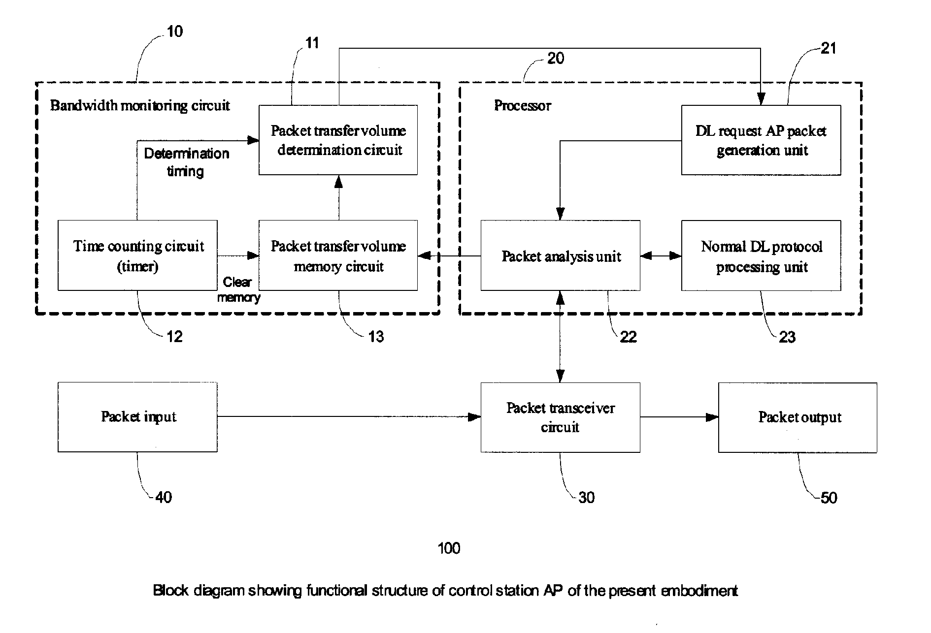
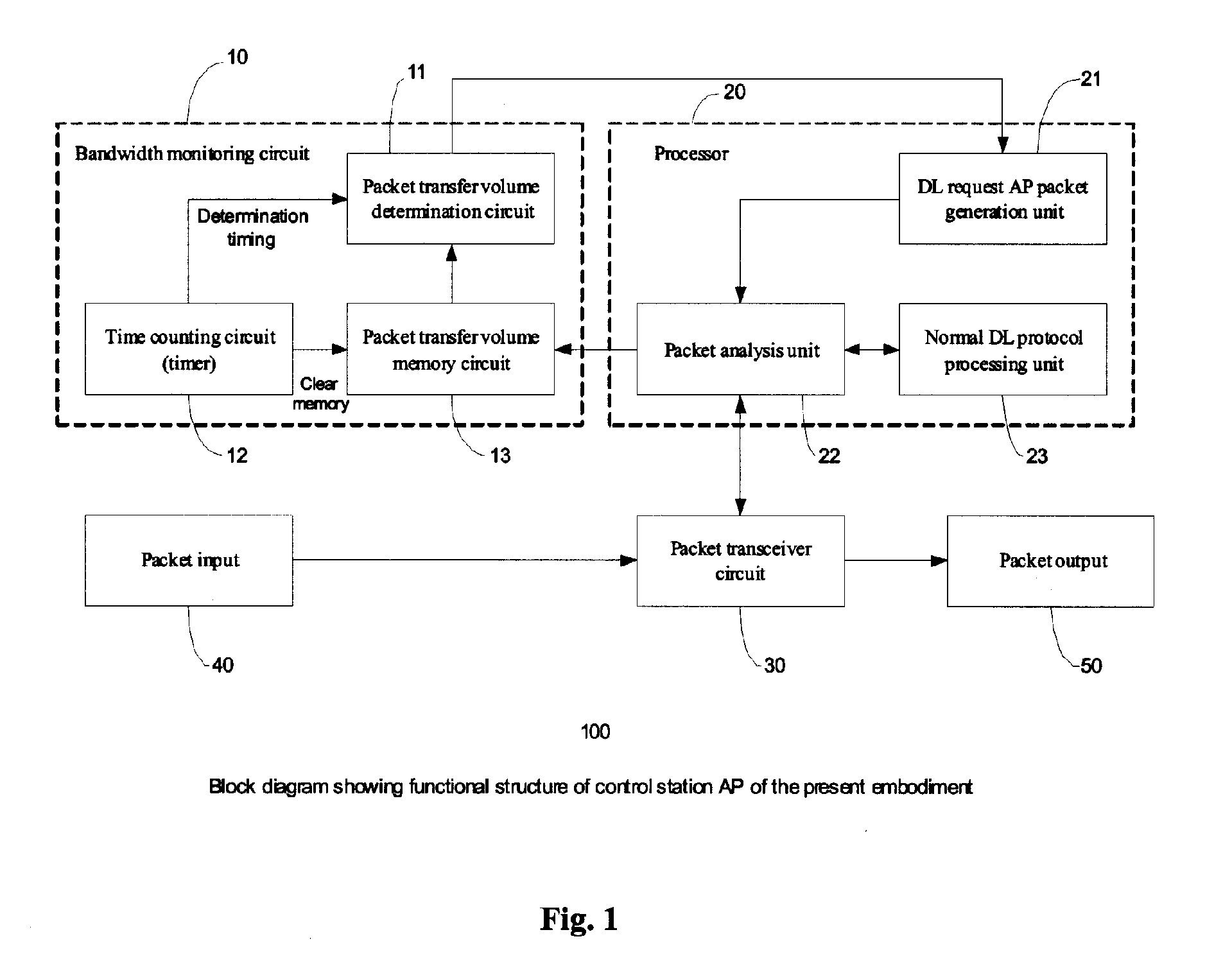
[0039]FIG. 1 is a block diagram showing the functional structure of the control station AP100 in an embodiment of the present invention. The control station AP100 of the present embodiment has a configuration in which a bandwidth monitoring circuit 10 and a DL request AP packet generation unit 21 are added to the conventional control station AP300 shown in FIG. 13.

[0040] Specifically, the control station AP100 of the present embodiment is provided with a packet input 40 to which a data packet is fed from a wireless receiver not shown in the diagram, a packet transceiver circuit 30 (data communication unit), which sends and receives a packet to and from a processor 20, a packet output 50, which feeds a packet to a wireless transmitter not shown in the diagram, and a bandwidth monitoring circuit 10.

[0041] The bandwidth monitoring circuit 10 is provided with a packet transfer volume memory circuit 13, which stores the packet volume transferred in a predetermined period of time betwee...


PUM


Abstract

The present invention provides a wireless communication system, a control station, and a terminal station whereby a direct link (DL) protocol can be initiated from the control station. A processor has a DL request AP packet generation unit (direct communication request generation instruction unit), which issues an instruction so that a direct link (direct communication) to a terminal station is established according to a notification issued from a packet transfer volume determination circuit when a packet transfer volume stored in a packet transfer volume memory circuit exceeds a predetermined threshold value.

Description

CROSS REFERENCE TO RELATED APPLICATION [0001] The present application claims priority under the Paris Convention to Japanese Patent Application No. 2004-222309, filed on Jul. 29, 2004. BACKGROUND OF THE INVENTION [0002] 1. Field of the Invention [0003] The present invention relates to a wireless communication system capable of improving communication traffic, to a control station, and to a terminal station. [0004] 2. Description of the Related Art [0005]FIG. 13 is a block diagram showing the functional structure of a control station (base station: access point) AP300 in the conventional wireless LAN system (IEEE 802.11b / a) in common use. The conventional control station 300 is provided with a packet input 40 to which a data packet is fed from a wireless receiver not shown in the diagram, a packet transceiver circuit 30, which sends and receives a packet to and from a processor 20, and a packet output 50, which feeds a packet to a wireless transmitter not shown in the diagram, and ha...

Claims


Application Information

Patent Timeline
Patent Type & Authority Applications(United States)
IPC IPC(8): H04B7/00H04W76/02H04W84/12
CPCH04W84/12H04W76/023H04W76/14
Inventor MATSUMARU, MAKOTOUSUBA, HIDEMIONODERA, WATARU
Owner PIONEER CORP
Learn More