
Rejuvenation of refractory metal products

Inactive Publication Date: 2006-02-16
MATERION NEWTON INC
View PDF1 Cites 47 Cited by
  • Summary
  • Abstract
  • Description
  • Claims
  • Application Information

AI Technical Summary

Benefits of technology

to replace current recycling processes by the rejuvenation of the refractory metal product (preferably a sputtering target). It is also an object of the invention to improve the cost and speed of getting used sputtering targets back into service. Finally, it is a further object of the invention to establish a microstructure of the fill zone at least as good as on the balance of the target.

Problems solved by technology

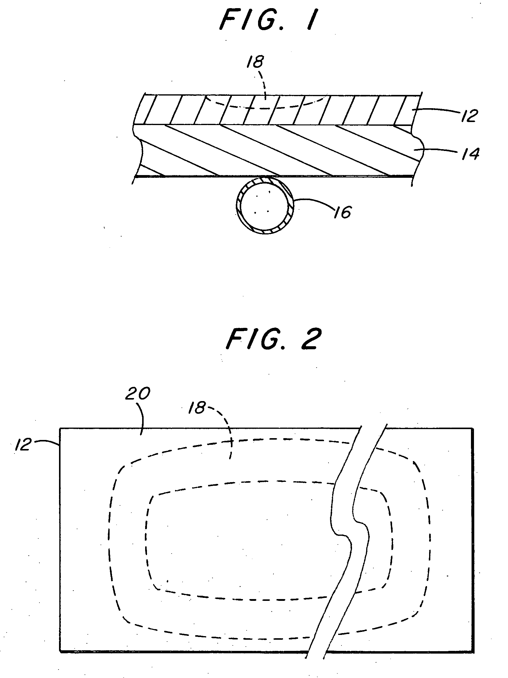
Sputtering targets of high temperature materials, such as tantalum and other refractory metals used in integrated circuit manufacture and other electrical, magnetic and optical product manufacture usually are eroded in a non-uniform way during the process of sputtering which leads to a race track like trench on the operating side of the target.

Method used


Image

  • Rejuvenation of refractory metal products
  • Rejuvenation of refractory metal products
  • Rejuvenation of refractory metal products

Examples


example 1

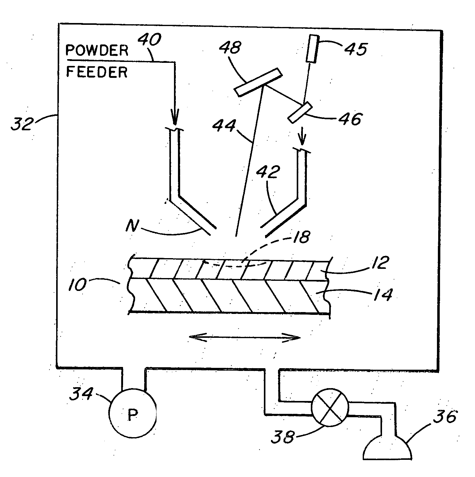
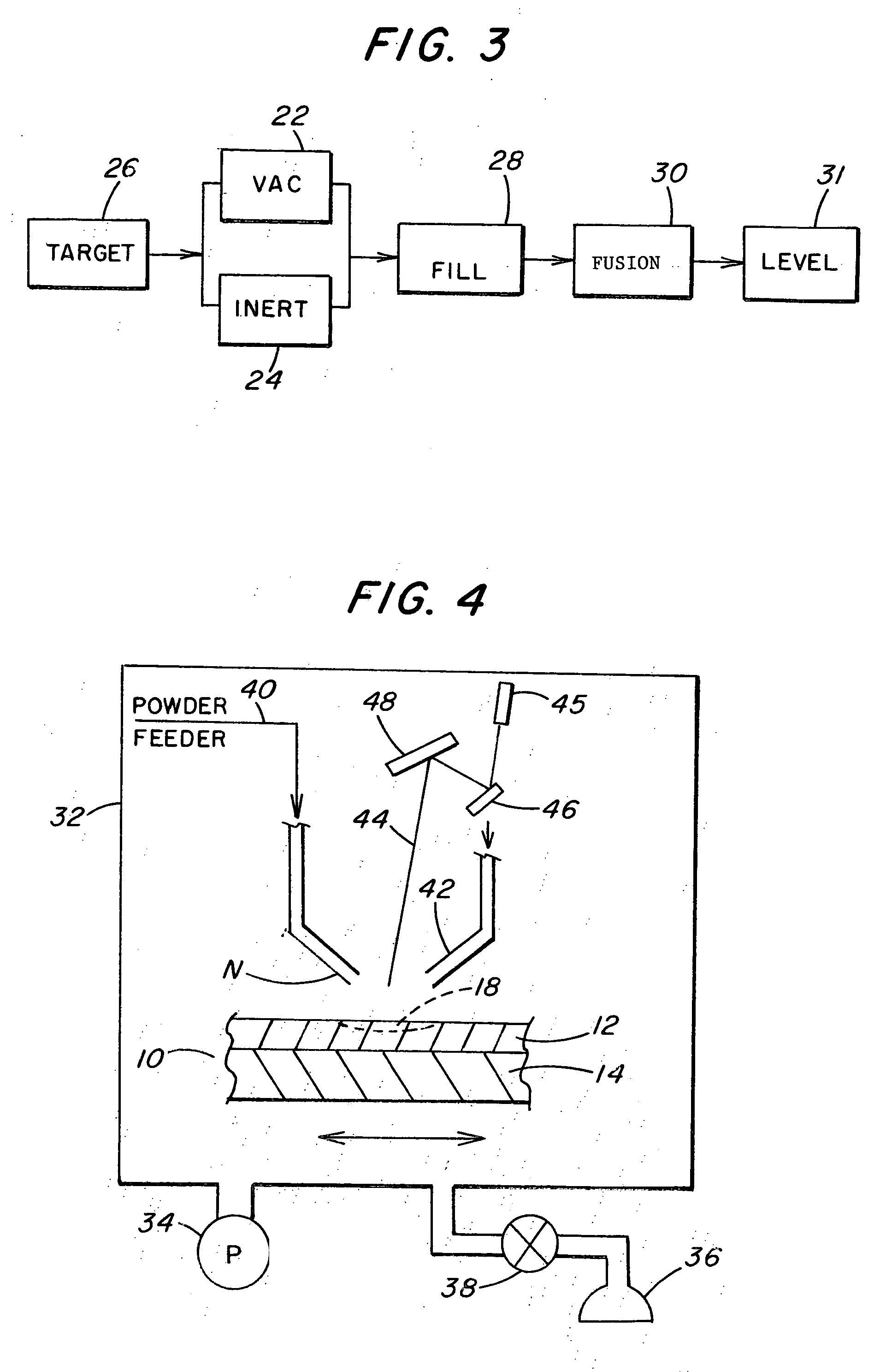
[0029] Rejuvenation was performed using a Trumph 3 KW Nd:YAG laser attached to a Fanuc M16i Robot. The entire assembly was contained in a stainless steel inert gas chamber with airlocks to prevent ingress of oxygen during part changeout. Process control was established using a CID camera to monitor the molten pool at the laser beam-powder-surface interface. Build quality was monitored using a conventional CCD camera. Two tantalum sputtering targets were fabricated by laser deposition of Ta powder on a tantalum substrate. The substrate was used to simulate a spent tantalum target. The deposits, approximately 105 mm in diameter and 5 mm thick, were made using an Nd:YAG laser operating at 2 KW and a powder flow rate of 1.9 mm3 / s. The tantalum powder stream and laser beam were cofocused, simultaneously applied and moved continuously such that layers of the fused and melted powder were built up to fill the void on the substrate and form a solid deposit. Once the void was filled and the d...


PUM

PropertyMeasurementUnit
Fractionaaaaaaaaaa
Fractionaaaaaaaaaa
Fractionaaaaaaaaaa

Abstract

Refractory metal products, such as tantalum, can be rejuvenated after metal consumption in selected zones by filling the zones with powder and simultaneously applying focused radiant energy to the powder.

Description

CROSS REFERENCE TO RELATED APPLICATIONS [0001] This application is a continuation-in-part application of U.S. application Ser. No. 10 / 075,709, filed on Feb. 14, 2002, which in turn claimed priority of Provisional Application No. 60 / 268,742, entitled “REJUVENATION OF SPUTTERING TARGETS” filed on Feb. 14, 2001, and which is incorporated herein by reference.BACKGROUND OF THE INVENTION [0002] The purpose of the invention is to decrease the recycling cost of refractory metal products, and, in particular, to rejuvenate sputtering targets having backing plate structures attached. [0003] Sputtering targets of high temperature materials, such as tantalum and other refractory metals used in integrated circuit manufacture and other electrical, magnetic and optical product manufacture usually are eroded in a non-uniform way during the process of sputtering which leads to a race track like trench on the operating side of the target. In order to prevent any contamination of the substrates or cata...

Claims


Application Information

Patent Timeline
IPC IPC(8): C23C14/32B22F7/06C23C14/34
CPCB22F7/062B22F2007/068B22F2999/00C23C14/3414H01J37/3491B22F3/1055Y02P10/25B22F10/32B22F10/28
Inventor AIMONE, PAUL R.KUMAR, PRABHATJEPSON, PETER R.UHLENHUT, HENNINGGOLDBERG, HOWARD V.MILLER, STEVEN A.
Owner MATERION NEWTON INC
Learn More