
Electrophotographic photoreceptor and image forming apparatus

a photoreceptor and photoreceptor technology, applied in the field of electrotrophotographic photoreceptor and image forming apparatus, can solve the problems of inability to achieve high-speed operation, reduce the sensitivity of the photoreceptor, and reduce the quality of the image to be formed, so as to achieve excellent wear resistance, no injuries, and durability and operation stability.

Active Publication Date: 2006-02-09
SHARP KK
View PDF5 Cites 6 Cited by
  • Summary
  • Abstract
  • Description
  • Claims
  • Application Information

AI Technical Summary

Benefits of technology

[0013] An object of the invention is to provide an electrophotographic photoreceptor excellent in wear resistance, durability and operation stability and capable of forming images with no injuries and unevenness in the density for a long period of time.
[0027] According to the invention, in the electrophotographic photoreceptor used for electrophotographic image formation and having a conductive substrate and an organic photosensitive layer, the surface physical property thereof is set such that the creep value CIτ is 2.70% or more, preferably, 3.00% or more, and the elastic work efficiency ηHU is 47% or more in a case where an indentation maximum load of 5 mN is loaded on the surface under a circumstance at a temperature of 25° C. and at a relative humidity of 50%. This can appropriately maintain the soft and flexibility of a film forming the surface layer of the electrophotographic photoreceptor, that is, balance between the viscosity and the elasticity, and provide a favorable state not fragile to external stress. Accordingly, since the amount of film reduction is decreased and the occurrence of injuries to the film is also decreased to keep the smoothness on the surface of the photoreceptor during long time use in which image formation of charging, exposure, development, transfer, cleaning and charge elimination is conducted repetitively, occurrence of injuries and unevenness in the density to the formed images can be prevented.
[0028] Further, since the photosensitive layer contains the compound represented by the structural formula (1), an electrophotographic photoreceptor excellent in wear resistance life and scratch resistance can be attained.
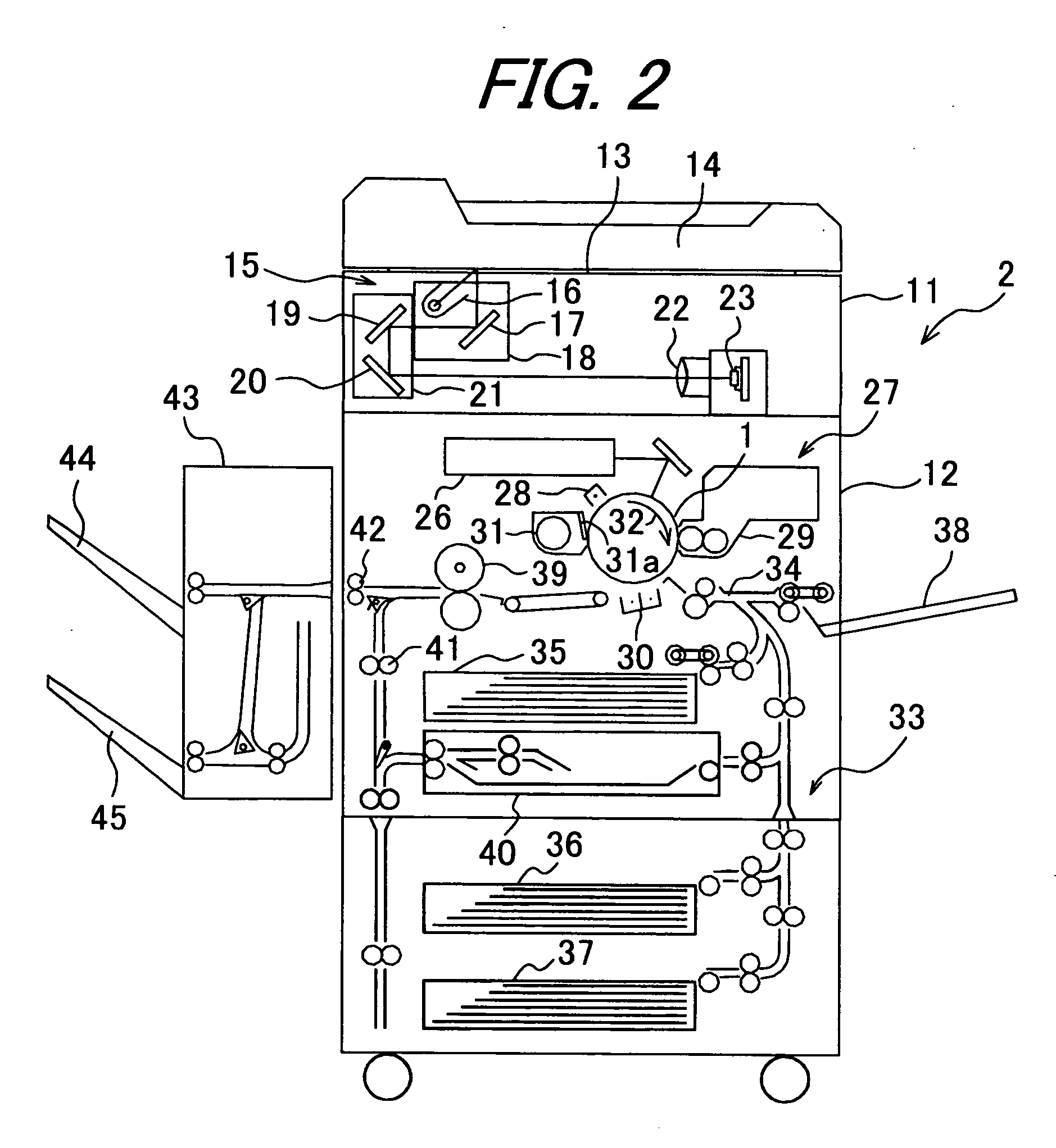
[0029] Further, according to the invention, since an electrophotographic photoreceptor of excellent wear resistance life and scratch resistance is provided, an image forming apparatus not causing injuries and unevenness in the density to the formed images for a long period of time can be attained.

Problems solved by technology

Since the residual toner and deposited paper dusts on the surface of the electrophotographic photoreceptor give adverse effects on quality of images to be formed, the residual toner and deposited paper dusts are removed by a cleaning device.
However, increase of the binder ratio decreases the sensitivity of the photoreceptor and this is not suitable to high speed operation.
Further, a binder of large molecular weight involves a problem of increasing the viscosity of a coating solution and thus leads to poor productivity.
However, any of the hardness tests described above involves a problem in measuring mechanical properties of a material sowing complicate behaviors of plasticity, elasticity (also including retarded component) and creeping property in combination.
For example, while Vicker's hardness is used for the evaluation of hardness of a film by measuring the length of an indentation, this reflects only the plasticity of the film and can not exactly evaluate a mechanical property showing a deformation state also including a large rate of elastic deformation such as an organic material.
Accordingly, even when the plastic deformation energy ratio is within the range described above, this can not always provide an organic photosensitive layer excellent in long time wear resistance, durability and operation stability.
Further, the electrophotographic photoreceptor of JP-A 2002-6526 involves a problem of increasing the cost in the formation of the protective layer containing the curable resin.

Method used


Image

  • Electrophotographic photoreceptor and image forming apparatus
  • Electrophotographic photoreceptor and image forming apparatus
  • Electrophotographic photoreceptor and image forming apparatus

Examples


example 1

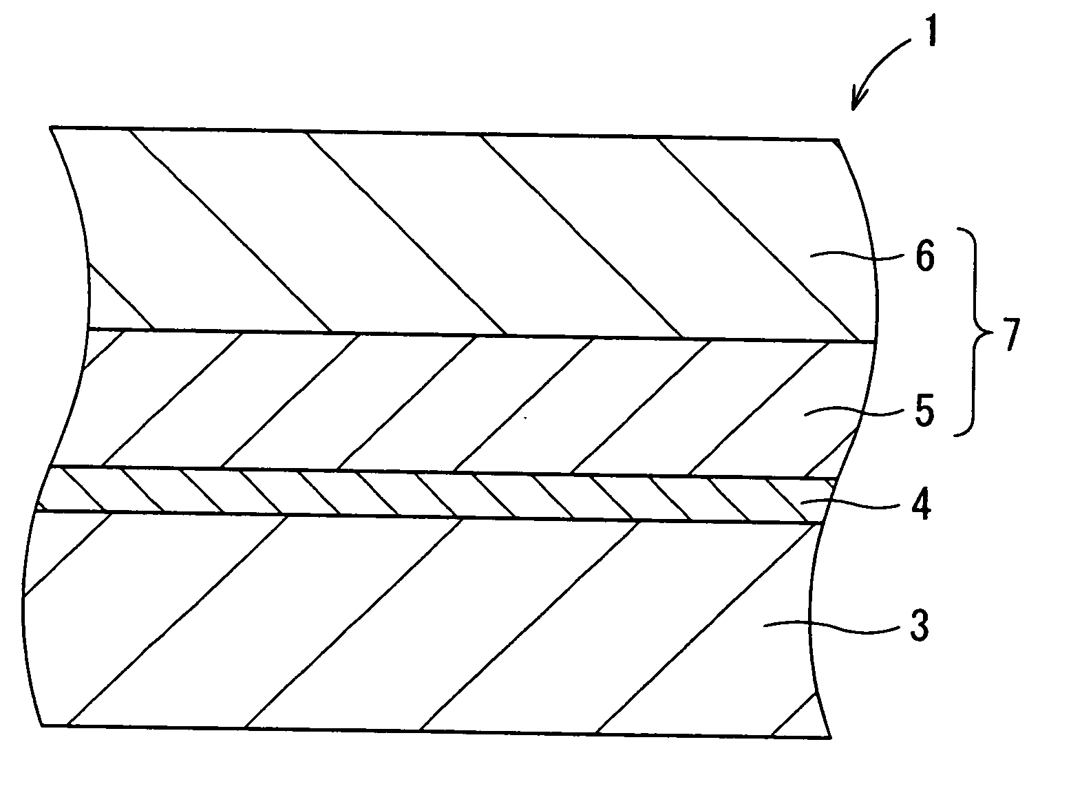
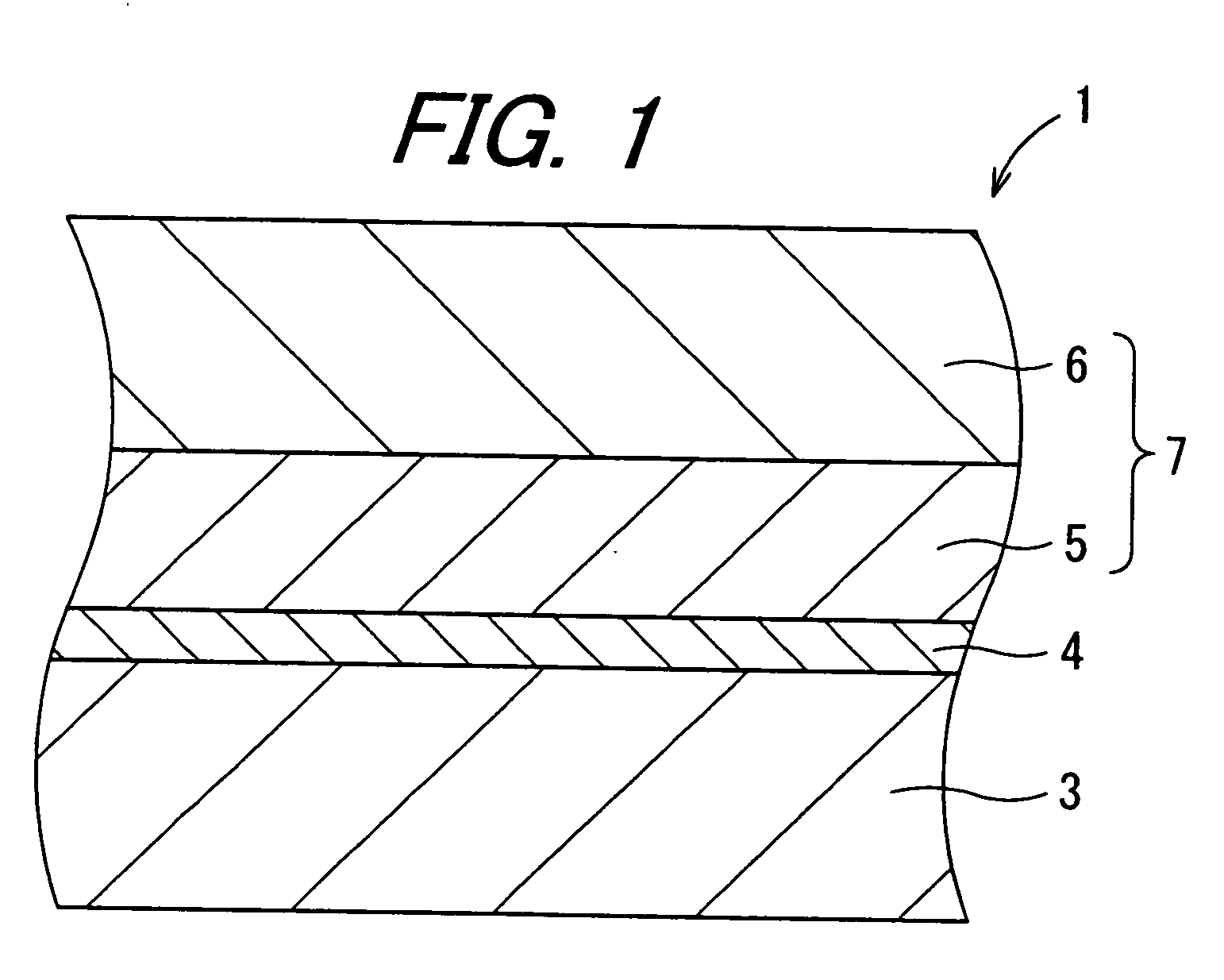
[0090] 3 parts of titanium oxide (TTO-MI-1) and 3 parts of an alcohol soluble nylon resin (CM 8000) were added to a mixed solvent of 60 parts of methyl alcohol and 40 parts of 1,3-dioxolane, the mixture was dispersed by a paint shaker for 10 hours to prepare a coating solution for undercoat layer. The coating solution was filled in a coating vessel, in which an aluminum cylindrical conducive support (diameter: 30 mm, length: 346 mm) was dipped and then taken up, spontaneously dried to form a undercoat layer having a layer thickness of 0.9 μm.

[0091] 10 parts of a butyral resin (S-LEC BL-2), 15 parts of titanyl phthalocyanine represented by the following structural formula (2) and 1400 parts of 1,3-dioxolane were dispersed by a ball mill for 72 hours, to prepare a coating solution for charge generating layer. The coating solution was coated on the undercoat layer by the dip coating method in the same manner as in the case of the undercoat layer and spontaneously dried to form a charg...

example 2

[0093] A photoreceptor was formed in the same manner as in Example 1 except for using a bisbutadiene compound represented by the following structural formula (3) as the charge transporting substance.

example 3

[0094] A photoreceptor was formed in the same manner as in Example 1 except for using 99 parts of a polycarbonate resin (GK-400) and 81 parts of a polycarbonate resin (GH503) as the binder resin for the charge transporting layer.


PUM


Abstract

An electrophotographic photoreceptor having an organic photosensitive layer at the surface layer is provided which can improve the wear resistance, durability and operation stability of the surface layer and can form images with no injury and unevenness in the density for a long period of time. The electrophotographic photoreceptor includes a conductive substrate, an undercoat layer, and a photosensitive layer having a charge generating layer and a charge transporting layer. In the photoreceptor, the photosensitive layer has a creep value CIτ of 2.70% or more and an elastic ratio ηHU of 47% or more in a case where an indentation maximum load of 5 mN is loaded on the surface under a circumstance at a temperature of 25° C. and at a relatively humidity of 50%.

Description

BACKGROUND OF THE INVENTION [0001] 1. Field of the Invention [0002] The present invention related to an electrophotographic photoreceptor and an image forming apparatus. [0003] 2. Description of the Related Art [0004] Electrophotographic image forming apparatus have been utilized not only for copying machines but also generally for printers as output means of computers, etc. for which demand has been remarkably increased in recent years. In electrophotographic image forming apparatus, a photosensitive layer of an electrophotographic photoreceptor provided to the apparatus is uniformly charged by a charger, exposing the same, for example, by a laser light corresponding to image information, and a finely particulate developer, which is called as a toner, is supplied to electrostatic latent images formed by exposure from a developing device, to form toner images. [0005] Although toner images formed by adhesion of the toner as a component of a developer to a surface of the electrophotog...

Claims


Application Information

Patent Timeline
Patent Type & Authority Applications(United States)
IPC IPC(8): G03G5/06
CPCG03G5/00G03G5/0596G03G5/0601G03G5/0672G03G5/0614G03G5/0666G03G5/0668G03G5/0605G03G5/061473G03G5/06149
Inventor KANAZAWA, TOMOKOFUKUSHIMA, KOTARO
Owner SHARP KK
Learn More