Stray field detector, magnetic disk drive, and method of head escaping
- Summary
- Abstract
- Description
- Claims
- Application Information
AI Technical Summary
Benefits of technology
Problems solved by technology
Method used
Image
Examples
first embodiment
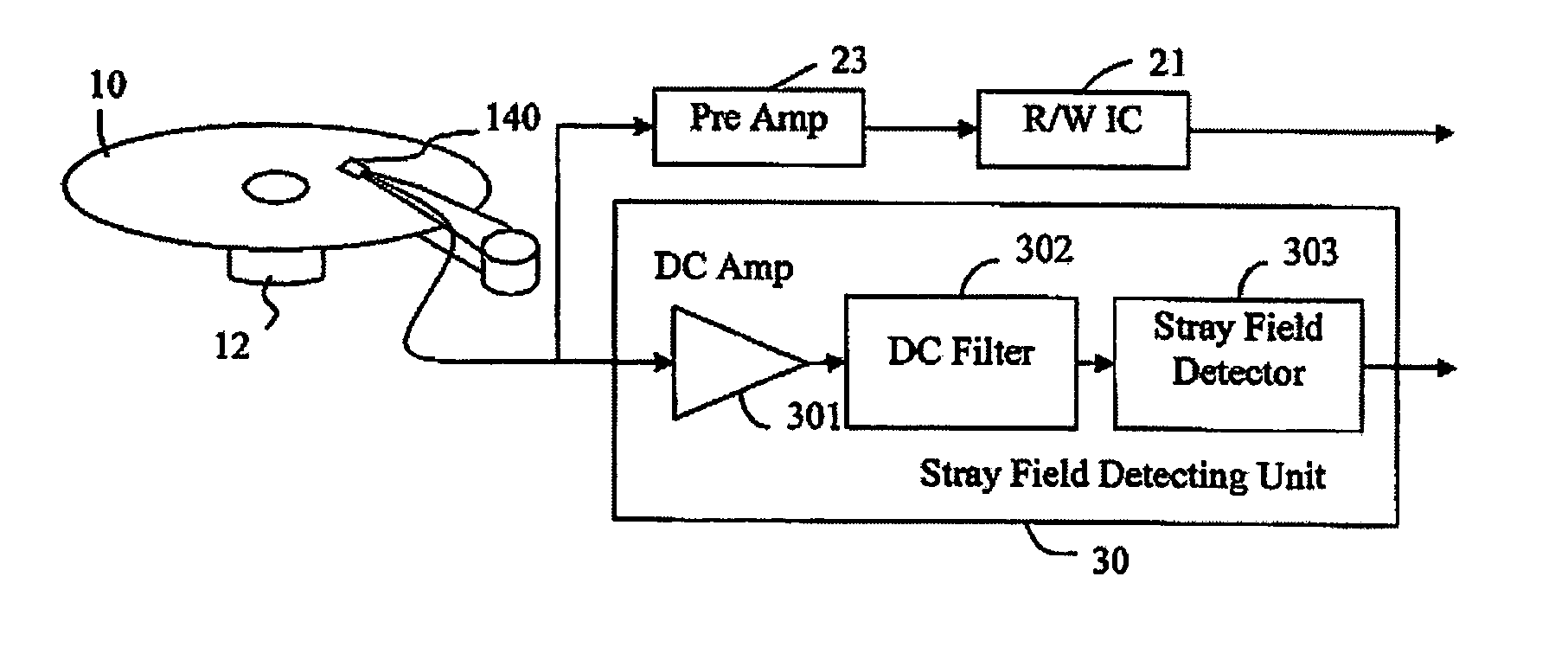
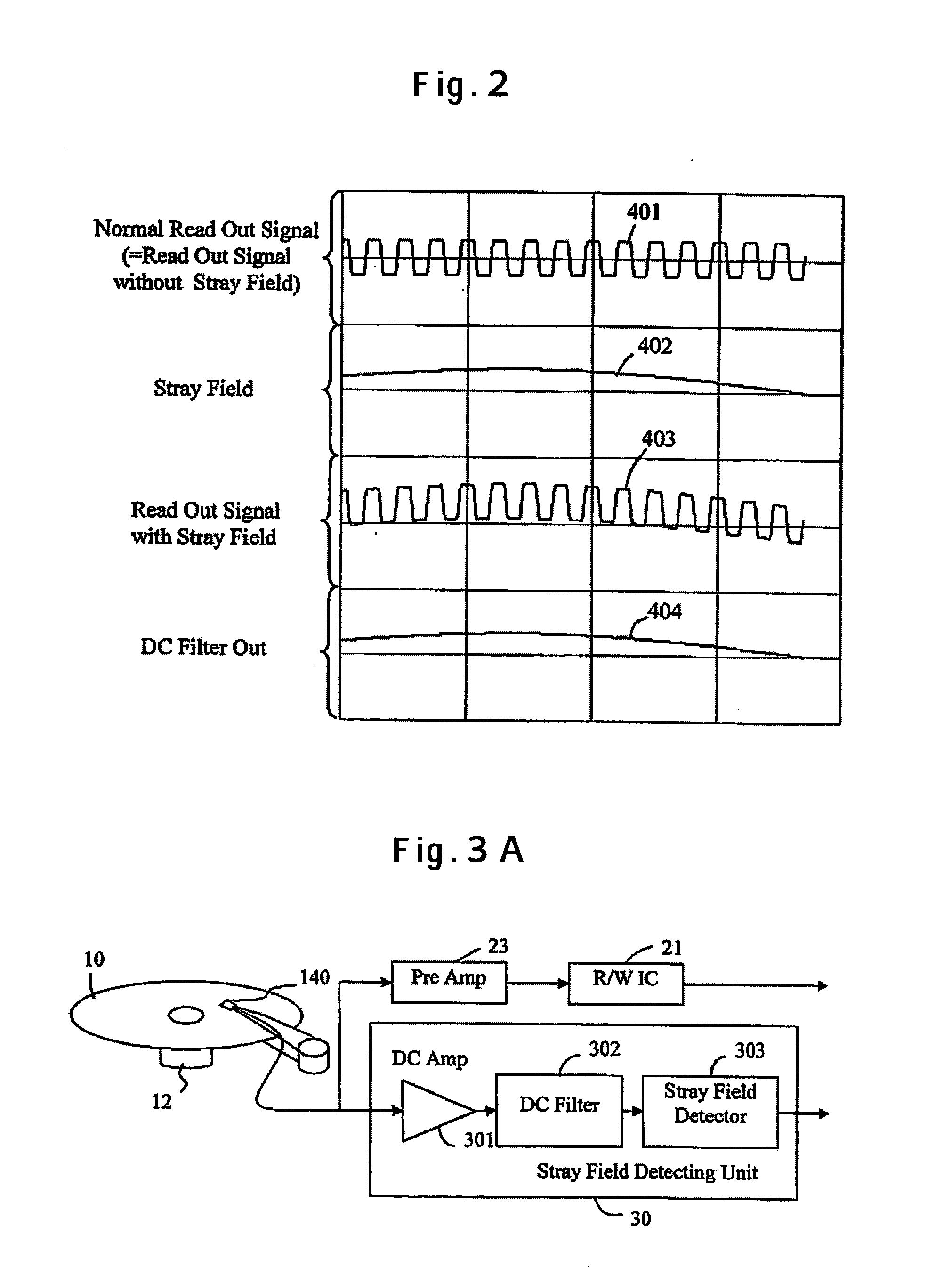
[0034] The embodiments of the present invention will be described with an application to a perpendicular magnetic disk drive. The stray field detecting method being the present invention will be described with reference to FIG. 1 and FIG. 2. The magnetic disk drive as shown in FIG. 1 includes a magnetic recording medium 10 that is driven to rotate by a motor 12, a head 140 that performs reading / writing to the magnetic recording medium 10, and a stray field detecting unit 30. The magnetic recording medium 10 is a double-layer perpendicular recording medium that has a magnetic recording layer and a soft under layer. The head 140 includes a single pole type head having a main pole and a return pole as the write head, and an MR element using a magneto-resistive effect such as the giant magneto-resistive effect and the tunneling magneto-resistive effect as the read head. The head 140 is mounted on a slider on the front of a suspension 151, and is positioned at a desired track on the magn...
second embodiment
[0038]FIG. 3A trough FIG. 3C illustrate constructions of the magnetic disk drive including the stray field detector being the present invention. FIG. 3A illustrates a construction that adds the stray field detecting unit 30 to the conventional signal processing circuit. The readout signal from the head 140 having the MR element is sent to a preamplifier 23 being the conventional signal processing circuit and an R / W IC 21, and so forth. In parallel to this, the readout signal from the head 140 is sent to the stray field detecting unit 30. Inside the stray field detecting unit 30, the output signal from the MR element is inputted to the DC Amp 301 in the same manner as the case with FIG. 1. The DC Amp 301 amplifies the signal containing the direct current and low frequency components, and the DC filter 302 passes only the amplified signal containing the direct current and low frequency components. The stray field detector 303 detects a stray field from this signal containing the direc...
third embodiment
[0042] Next, the third embodiment relates the signal outputted from the stray field detector. The stray field detector 303 detects the stray field intensity from the output of the DC filter 302. The stray field detector 303 is able to output the detected stray field intensity as it is.
[0043] It is also possible to set in a memory a threshold determined in advance from the direct current and low frequency signal of the MR output in the state that the stray field is not applied, and when the stray field exceeds the threshold, to send out from the stray field detector 303 a signal showing that a critical stray field to cause demagnetization or degaussing is applied. It is possible to uniquely determine this threshold by the combination of the head and magnetic recording medium; however, since the resistance of the MR element varies depending on the temperature, it may be arranged to set several thresholds based on the relation between the temperature inside the drive, the operation tim...
PUM
 Abstract
Description
Claims
Application Information
 - R&D
- Intellectual Property
- Life Sciences
- Materials
- Tech Scout
- Unparalleled Data Quality
- Higher Quality Content
- 60% Fewer Hallucinations
Browse by: Latest US Patents, China's latest patents, Technical Efficacy Thesaurus, Application Domain, Technology Topic, Popular Technical Reports.
© 2025 PatSnap. All rights reserved.Legal|Privacy policy|Modern Slavery Act Transparency Statement|Sitemap|About US| Contact US: help@patsnap.com


