Radio telephone apparatus and method for controlling amount of electric current consumption thereof
a radio telephone and electric current technology, applied in the field of radio telephone equipment, can solve the problems of large amount of electric current, difficulty in hearing a voice by a heating-impaired person, and increased level of development of magnetic field, and achieve the effect of reducing weigh
- Summary
- Abstract
- Description
- Claims
- Application Information
AI Technical Summary
Benefits of technology
Problems solved by technology
Method used
Image
Examples
first embodiment
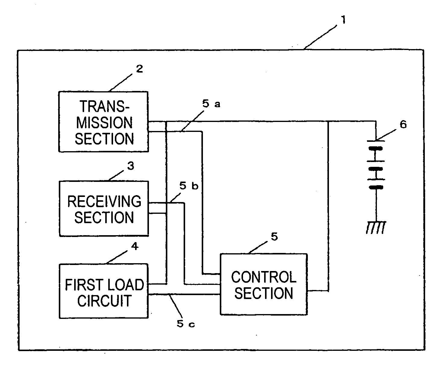
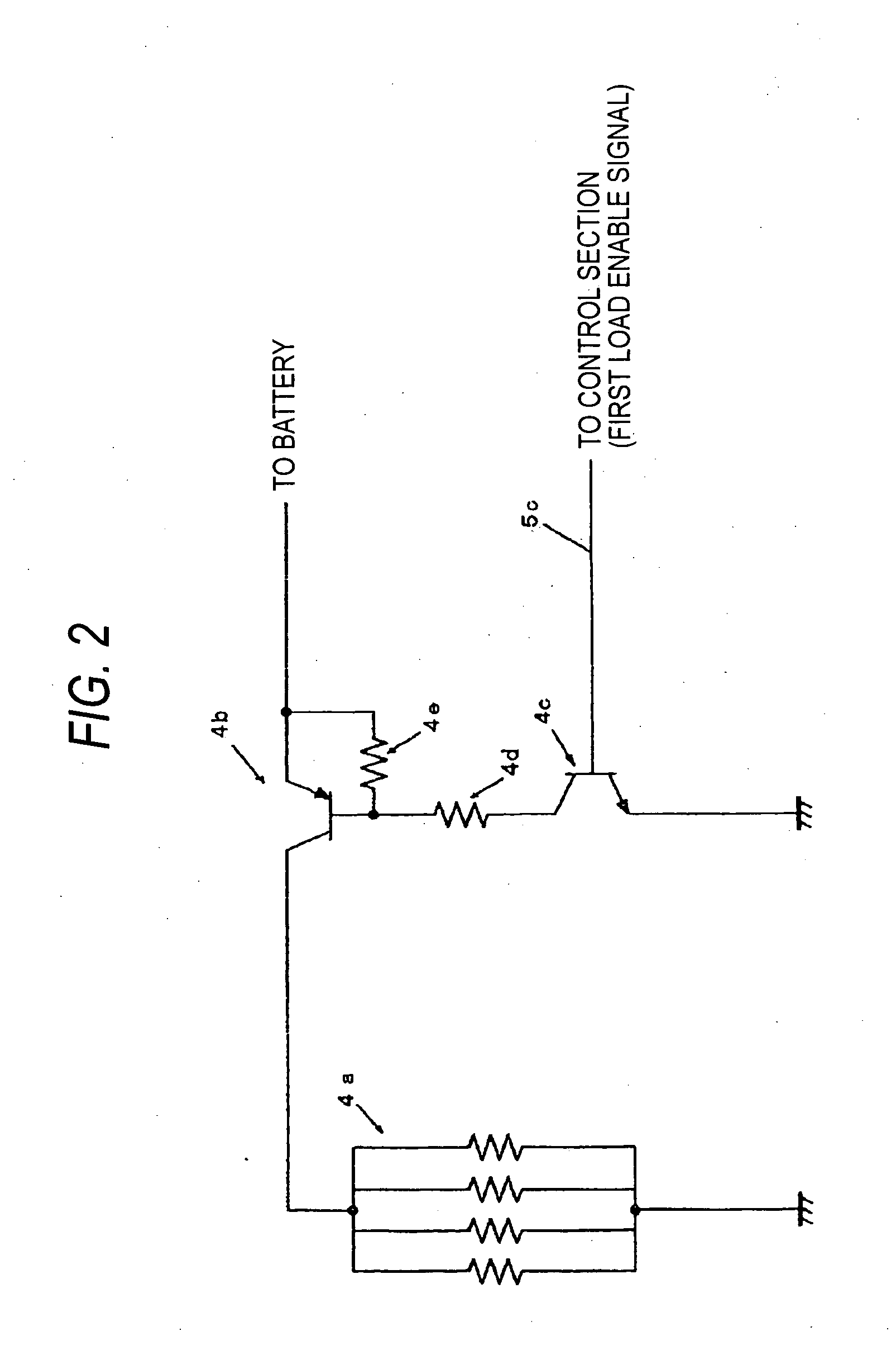
[0046] The configuration of a portable cellular phone which is a radio telephone apparatus according to a first embodiment of the present invention will be described by reference to FIGS. 1 through 3. FIG. 1 is a view for describing a portable cellular phone which is an example of the radio telephone apparatus according to the first embodiment of the present invention. FIG. 2 is a view for describing an example of a load circuit used in the radio telephone apparatus according to the first embodiment of the present invention. FIG. 3 is a view for describing a transmission section, a receiving section, and a load circuit, which are arranged on a substrate of the radio telephone apparatus according to the first embodiment of the present invention.
[0047] A portable cellular phone 1 establishes digital communication with a base station by compressing voice data. This communication is effected by a time-division slot, wherein a transmission slot for transmitting a radio wave to the base ...
second embodiment
[0086] The configuration of a portable cellular phone, which is an embodiment of a radio telephone apparatus according to a second embodiment of the present invention, will be described by reference to FIG. 7. FIG. 7 is a view for describing the portable cellular phone, which is an example of the radio telephone apparatus of the second embodiment of the present invention. In FIG. 7, the transmission section 2, the receiving section 3, and the battery 6, all of which are shown in FIG. 1, have the same configurations, and hence they are assigned the same reference numerals, and their explanations are omitted.
[0087] As shown in FIG. 7, a portable cellular phone 15 includes a second load circuit 16 and a third load circuit 17. The second load circuit 16 is a circuit which consumes the same amount of electric current as that consumed by the transmission section 2. The third load circuit 17 is a circuit which consumes a difference current between the electric current consumed by the tran...
third embodiment
[0102]FIG. 10 is a configuration example of hardware for implementing the portable cellular phone 1. The IC 201 is a microprocessor IC for controlling the portable cellular phone 1. Terminals 1 and 2 are for recharging the portable cellular phone 1. Electric currents input by way of the terminals 1 and 2 are subjected to bridge rectification in diodes D205 to D208 and employed as an electric current actually used for recharging operation or operating respective electronic components. Even when the terminals are reversely connected, the bridge rectification circuit can perform recharging operation and activate equipment with correct polarities.
[0103] At this time, the signal having passed by a diode 0213 flows through a transistor Q207, and is used as a signal for determining whether or not the microprocessor IC 202 is performing recharging operation. The microprocessor IC 201 controls a transistor Q212 by the signal having passed through transistors Q209 and Q210, both of which are...
PUM
 Abstract
Description
Claims
Application Information
 - R&D
- Intellectual Property
- Life Sciences
- Materials
- Tech Scout
- Unparalleled Data Quality
- Higher Quality Content
- 60% Fewer Hallucinations
Browse by: Latest US Patents, China's latest patents, Technical Efficacy Thesaurus, Application Domain, Technology Topic, Popular Technical Reports.
© 2025 PatSnap. All rights reserved.Legal|Privacy policy|Modern Slavery Act Transparency Statement|Sitemap|About US| Contact US: help@patsnap.com


