
Method and system for calibrating a reflection infrared densitometer in a digital image reproduction machine

a technology of infrared densitometer and digital image reproduction machine, which is applied in the direction of optical radiation measurement, instruments, electrographic process, etc., can solve the problems that the controller's dma regulation may become too inaccurate for acceptable image quality, and the increase in led intensity alters the diffuse signal, so as to increase the density range of toner patches. , the effect of increasing the densities of toner patches

Active Publication Date: 2006-02-02
XEROX CORP
View PDF8 Cites 18 Cited by
  • Summary
  • Abstract
  • Description
  • Claims
  • Application Information

AI Technical Summary

Benefits of technology

The present invention provides an ETAC calibration method for accurate DMA measurements using ETAC sensor signals. The method includes generating image panels with toner patches of incrementally increasing densities on a photoreceptor medium, obtaining specular readings and diffuse readings for light reflected from the toner patches, computing specular DMAs and determining a functional relationship between the specular DMAs and the diffuse readings. The calibration method can be executed at any time and can be used to determine the functional relationship between the specular DMAs and the diffuse readings. The system includes a raster output scanner, an enhanced toner area coverage sensor, and a controller for computing specular DMAs and determining the functional relationship. The calibration method can be used to improve the accuracy of DMA measurements in a digital reproduction system.

Problems solved by technology

However, the increase in LED intensity alters the diffuse signals and the DMA measurements obtained from an ETAC sensor.
Thus, the controller's regulation of DMA may become too inaccurate for acceptable image quality.

Method used


Image

  • Method and system for calibrating a reflection infrared densitometer in a digital image reproduction machine
  • Method and system for calibrating a reflection infrared densitometer in a digital image reproduction machine
  • Method and system for calibrating a reflection infrared densitometer in a digital image reproduction machine

Examples


Embodiment Construction

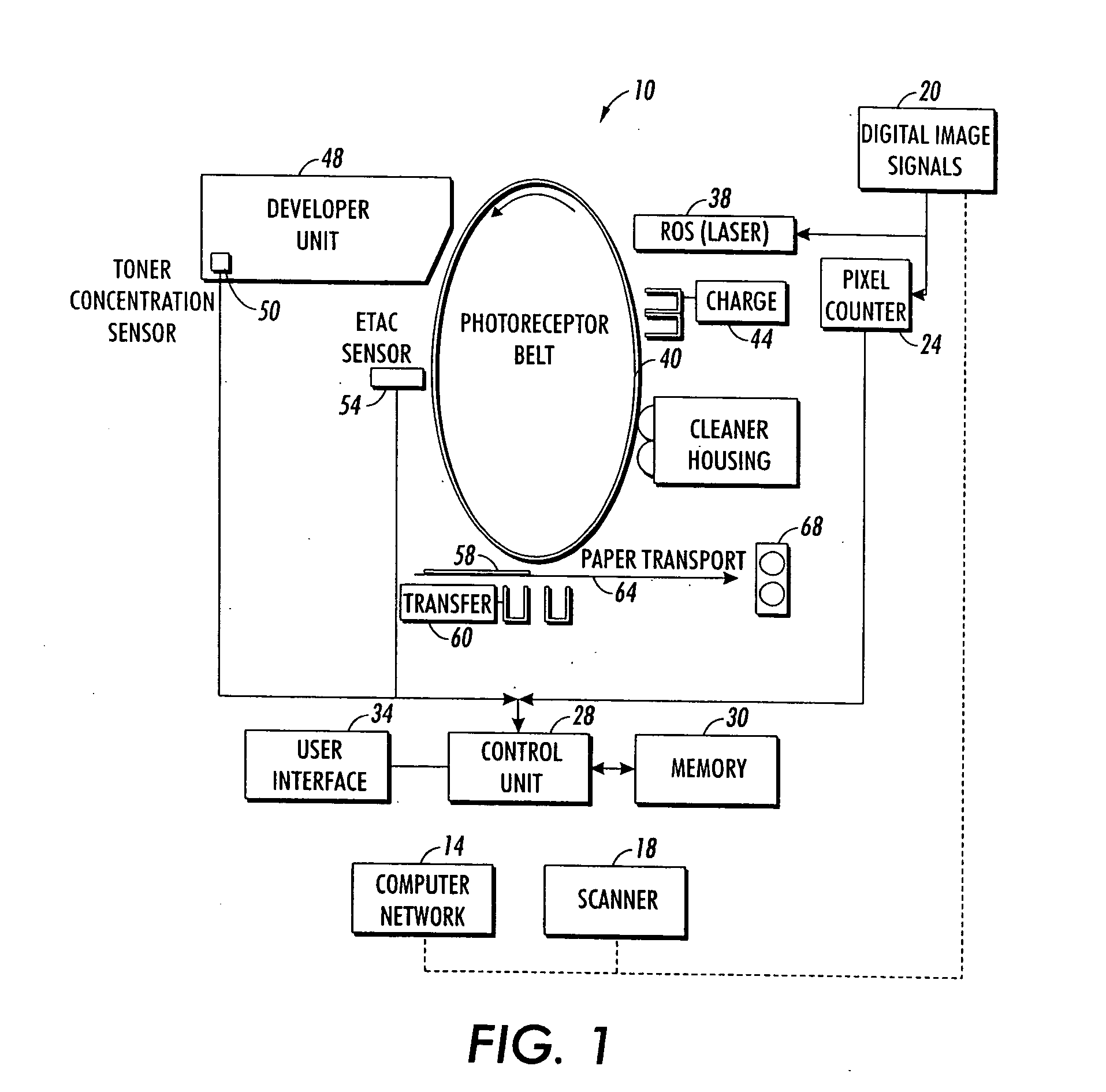
[0020]FIG. 1 shows a digital document reproduction system in which the calibration of the present invention may be used. The system 10 may include a computer network 14 through which digital documents are received from computers, scanners, and other digital document generators. Also, digital document generators, such as scanner 18, may be coupled to the digital image receiver 20. The data of the digital document images are provided to a pixel counter 24 that is also coupled to a controller 28 having a memory 30 and a user interface 34. The digital document image data is also used to drive the raster output scanner 38. The photoreceptor belt 40 rotates in the direction shown in FIG. 1 for the development of the latent image and the transfer of toner from the latent image to the support material.

[0021] To generate a hard copy of a digital document, the photoreceptor belt is charged using corona discharger 44 and then exposed to the ROS 38 to form a latent image on the photoreceptor b...


PUM


Abstract

An enhanced toner area coverage (ETAC) sensor may be calibrated to adjust for changes in LED intensity by determining a functional relationship between specular developed mass per unit area (DMA) values and diffuse readings obtained from the sensor. Specular and diffuse readings are obtained from an ETAC sensor that senses reflected light from toner patches generated with incrementally increasing densities on the photoreceptor belt. The specular readings in a particular range and their corresponding diffuse readings are selected for the calibration computations. Reflected ratios are computed from the specular readings and used to determine specular DMAs. The specular DMAs and selected diffuse readings define a set of points for which a functional relationship is determined.

Description

FIELD OF THE INVENTION [0001] The present invention relates generally to digital document production systems, and more particularly, to digital document production systems that use reflection infrared densitometers to monitor and control the document reproduction process. BACKGROUND OF THE INVENTION [0002] Digital document reproduction systems are well-known. These systems typically include a digital document generator that may be coupled to the reproduction system directly or through a computer network. Digital document generators include computers, scanners, or other devices that store or permit a user to define content for a digital document. The digital data are provided to a print engine so the controller of the engine may control the process. The reproduction system also includes a photoreceptor belt or drum that provides a rotating surface for the development and transfer of a latent image that corresponds to the digital document. [0003] The latent image development begins wi...

Claims


Application Information

Patent Timeline
Patent Type & Authority Applications(United States)
IPC IPC(8): G03G15/00
CPCG03G15/5041
Inventor SCHEUER, MARK A.DONALDSON, PATRICIA J.KRECKEL, DOUGLAS A.
Owner XEROX CORP
Learn More