
Process for the treatment of a hydrocarbon feedstock

a hydrocarbon feedstock and hydrocarbon oil technology, applied in the direction of hydrocarbon oil cracking process, thermal non-catalytic cracking, etc., can solve the problems of limited hydrogen purity, significant quantity of lpg is evacuated, and the purity of lpg is limited, so as to maximize the recovery of lpg and minimize the loss of lpg

Active Publication Date: 2006-02-02
INST FR DU PETROLE
View PDF2 Cites 24 Cited by
  • Summary
  • Abstract
  • Description
  • Claims
  • Application Information

AI Technical Summary

Benefits of technology

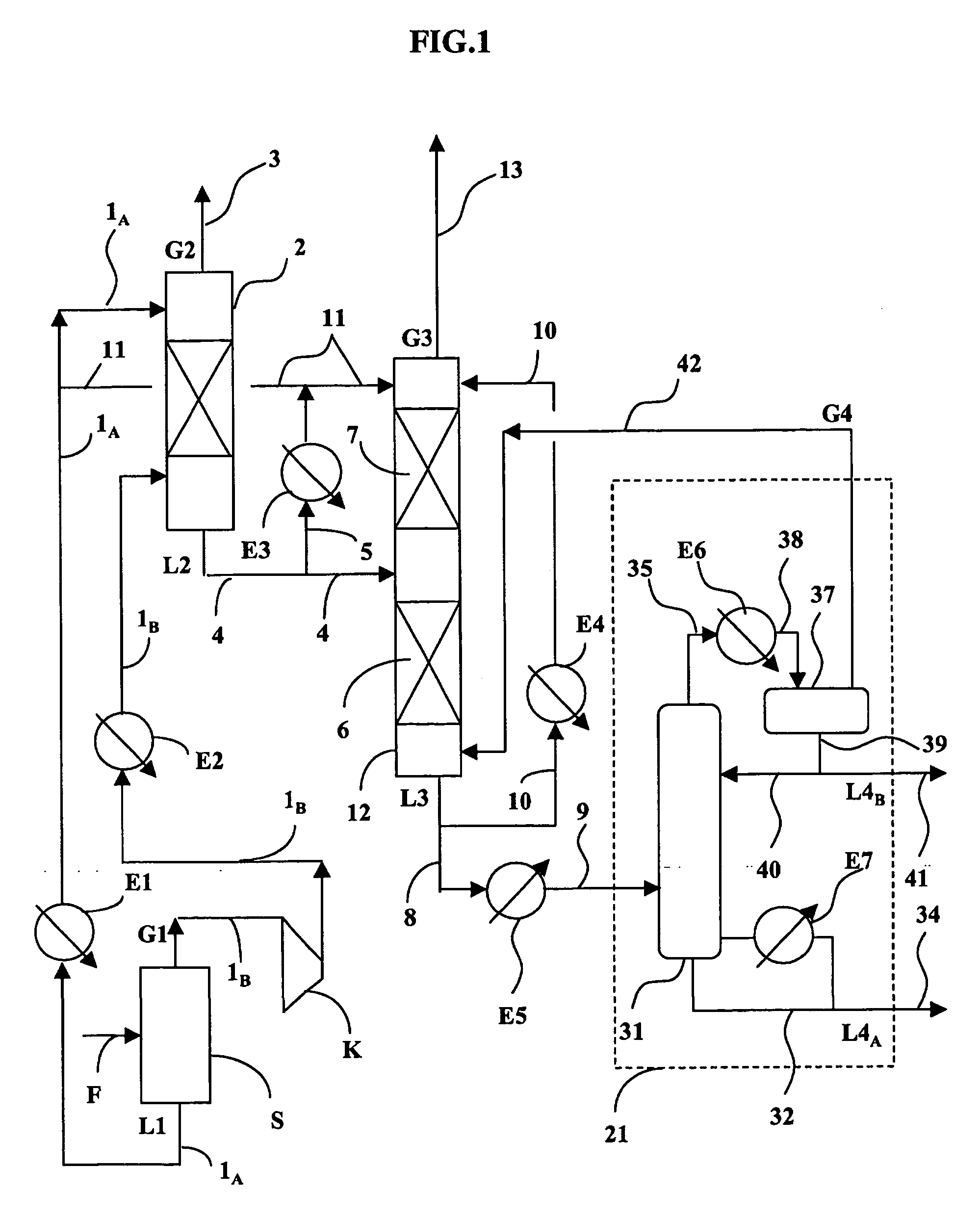
The invention proposes a process to economically maximize the recovery of liquefied petroleum gas (LPG) and minimize the losses of LPG in hydrogen-rich gaseous effluents or in fuel gas. This is achieved without oversizing the final distillation column. The invention proposes a method where LPG-rich gases are contacted with unstabilized reformate, which is carried out in countercurrent, and with reformate that is cooled below its bubble point and preferably below the ambient temperature. This method allows for the recovery of a large portion of LPG and the elimination of light compounds without oversizing the distillation column of the reformate.

Problems solved by technology

A problem that is posed by those techniques of the prior art that comprise intense elimination of light compounds (methane and / or ethane), so as to increase the purity of the hydrogen, is that a significant quantity of LPG is evacuated with the light gaseous effluent that is obtained during the stage for separation of recovered condensates, downstream from the recovery of the hydrogen-rich gas.
LPG is also often lost or allowed into the hydrogen-rich purified gas, which is harmful from the standpoint of the purity of the hydrogen.
The purity of the hydrogen is therefore limited, because the latter comprises the largest portion of methane and ethane.
Further, the separation arrangement is relatively complex.
It has already been proposed to contact the first gaseous effluent by the stabilized reformate, but this technical option is expensive at the level of the reformate / LPG downstream fractionation.

Method used


Image

  • Process for the treatment of a hydrocarbon feedstock

Examples


example 1

FOR COMPARISON

[0058] A catalytic reforming effluent that exits under a pressure of 0.5 MPa is fed into an installation of the prior art according to a process that is not in accordance with that of the invention, for which the pieces of equipment differ from those of FIG. 1 in that pieces of equipment 2 and 12 are not columns but simple gas / liquid separator tanks that are fed at an ambient temperature of 31° C. Lines 1A and 1B are then merged at the inlet of the separator tank that replaces column 2. In an analogous way, column 12 is replaced by a simple separator tank; lines 5, 11 and 10 are eliminated, and gas G4 is mixed in line 4 that is upstream from the separator tank with liquid L2, at 31° C., that is obtained from the first separator tank. The flows that enter into the separator tank are provided in Table 1:

TABLE 1Kg / hInput (5)Liquid Output (8)Gas Output (13)H2291019C128322855C223822251131C33613355062iC41682167012NC42550253713C5+889998898316Total Kg / h9953899229309Pressure ...

example 2

ACCORDING TO THE INVENTION

[0059] The installation of Example 1 is used with the consistent modification to replace the (second) separator tank by an absorption column 12. This column comprises a single absorption zone 7 with 5 theoretical stages (whereby zone 6 that is shown in FIG. 1 is eliminated). A liquid AL2 that represents 5% by mass (or 5100 kg / h) of liquid flow L3 that exits from the column via pipe 8 is sampled via line 10, cooled to −5° C. in exchanger E4 and reinjected at the top of the column. The operating conditions are indicated in Table 2.

TABLE 2Kg / hInput (5)Liquid Output (8)Gas Output (13)H228919C131225160C23403330794C34688465834iC4199019865NC4290128975C5+89268892614Total Kg / h102590102369221Pressure MPa1.61.61.5Temperature ° C.35340

[0060] The comparison of Tables 1 and 2 shows that the loss in LPG in the column top gas (line 13) drops from 87 kg / h to 44 kg / h by using the invention and is therefore essentially reduced by half.


PUM

PropertyMeasurementUnit
temperatureaaaaaaaaaa

Abstract

Process for treatment of a hydrocarbon feedstock that comprises a hydrocarbon-containing liquid phase and hydrogen, in which the feedstock is separated under a pressure P1 into a liquid L1 and a gas G1, that is compressed and brought into contact with a portion of L1 under a pressure P2>2×P1 to recover a liquid L2 and a hydrogen-rich gas G2; L2 is fractionated to obtain a stabilized liquid L4a that is free of LPG and lighter products, a liquid stream of LPG, and a gas stream G4 that is recycled, and in which one of gas streams: recompressed G1 and G4 is in counter-current contact with an unstabilized liquid AL that is obtained from or extracted from L1 or L2, whereby this unstabilized liquid is supercooled by at least 10° C. below its bubble point at pressure P2.

Description

FIELD OF THE INVENTION [0001] The invention relates to the field of treatments of effluents of petroleum or petrochemical refining or conversion units, whose effluents comprise both hydrogen and hydrocarbons such as: methane, ethane, propane, butane, fractions of hydrocarbons that have 5 to 11 carbon atoms (designated by C5-C11), and optionally heavier hydrocarbons such as hydrocarbons that have between 12 and 30 carbon atoms (C12-C30) and even more, often in a small quantity. [0002] It can involve in particular the treatment of an effluent for catalytic reforming or aromatization of fractions that boil in the field of gasoline (that have essentially 6 to 11 carbon atoms), making it possible to recover an aromatic reformate, a hydrogen-rich gas, and a liquefied petroleum gas (product that we will designate by “LPG,” essentially comprising hydrocarbons with three or four carbon atoms: propane and / or propylene and / or butane and / or butenes and / or butadiene, as well as mixtures thereof)...

Claims


Application Information

Patent Timeline
Patent Type & Authority Applications(United States)
IPC IPC(8): C10G5/00C10G35/04C10G49/22
CPCC10G49/22C10G35/04
Inventor SANCHEZ, ERICFISCHER, BEATRICE
Owner INST FR DU PETROLE
Learn More